Great Planes Easy Sport 40 ARF MonoKote - GPMA1036 User Manual
Page 14
hinge. Turn the fuselage over and apply six more drops of thin
CA to the other side of each hinge. DO NOT use accelerator
while hinging, as the CA must wick into the hinge to properly
attach the hinges. Use a paper towel to absorb any excess
CA. After the CA cures, flex the elevators in both directions to
free up the elevators for operation.
❏
5. Carefully cut a slot in the tail post using a hobby knife
for the lower rudder hinge.
❏
6. Temporarily install the rudder to determine where to
notch the rudder to allow clearance for the elevator joiner.
Press the rudder gently to leave an impression of the joiner
on the rudder. Remove the rudder and cut a notch that is
1/16" [1.6mm] above and below the impression. The notch
should be cut 1/4" [6.4mm] deep.
❏
7. Reinstall the rudder and make sure that the notch
allows proper clearance for the elevator joiner to operate
without binding when the rudder is fully deflected. Also, the
edges of the notch may need to be beveled to allow for full
movement of the rudder. Once you are satisfied that there
is no binding, glue the hinges using the same technique as
the elevator hinges.
❏
8. Glue the ailerons to the wing using the same
technique. Be sure to glue the torque rods in place with
6-minute epoxy.
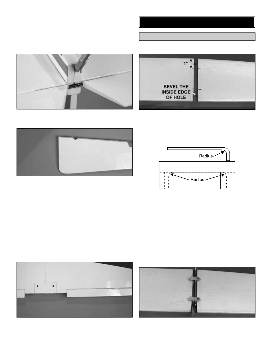
REFER TO THIS PHOTO FOR THE FOLLOWING 3 STEPS
❏
1. Locate the groove for the main landing gear under the
covering in the center of the fuselage by lightly pressing
with your finger. Using a hobby knife, carefully remove the
covering, exposing the groove.
Note: Do not cut into the wood around the groove.
❏
2. Carve a slight bevel on the inside edge of both holes.
This is to allow for the radius at the bend in the landing gear.
❏
3. To prevent fuel from damaging the exposed wood, a
thin coat of thin CA should be applied. This can be done by
applying the CA, then using a piece of waxed paper or
plastic, spread the glue until the wood has been completely
covered by the CA.
❏
4. Measure in 1" [25.4] from the outside edges of the
fuselage at the landing gear groove to locate the position of
the landing gear straps. Drill a 1/16" [1.6mm] hole 3/32"
[2.4mm] from the rear edge only at this time.
❏
5. Install the main landing gear into position. Install the
landing gear straps using two of the #2 x 3/8" [9.5mm] screws.
Note:Do not tighten the screws yet.
Mount the Main Landing Gear
INSTALL THE LANDING GEAR
14