GME TX3440 User Manual
Page 19
t X 3 4 4 0
i n s t r u c t i o n m A n uA l
PA G E 1 9
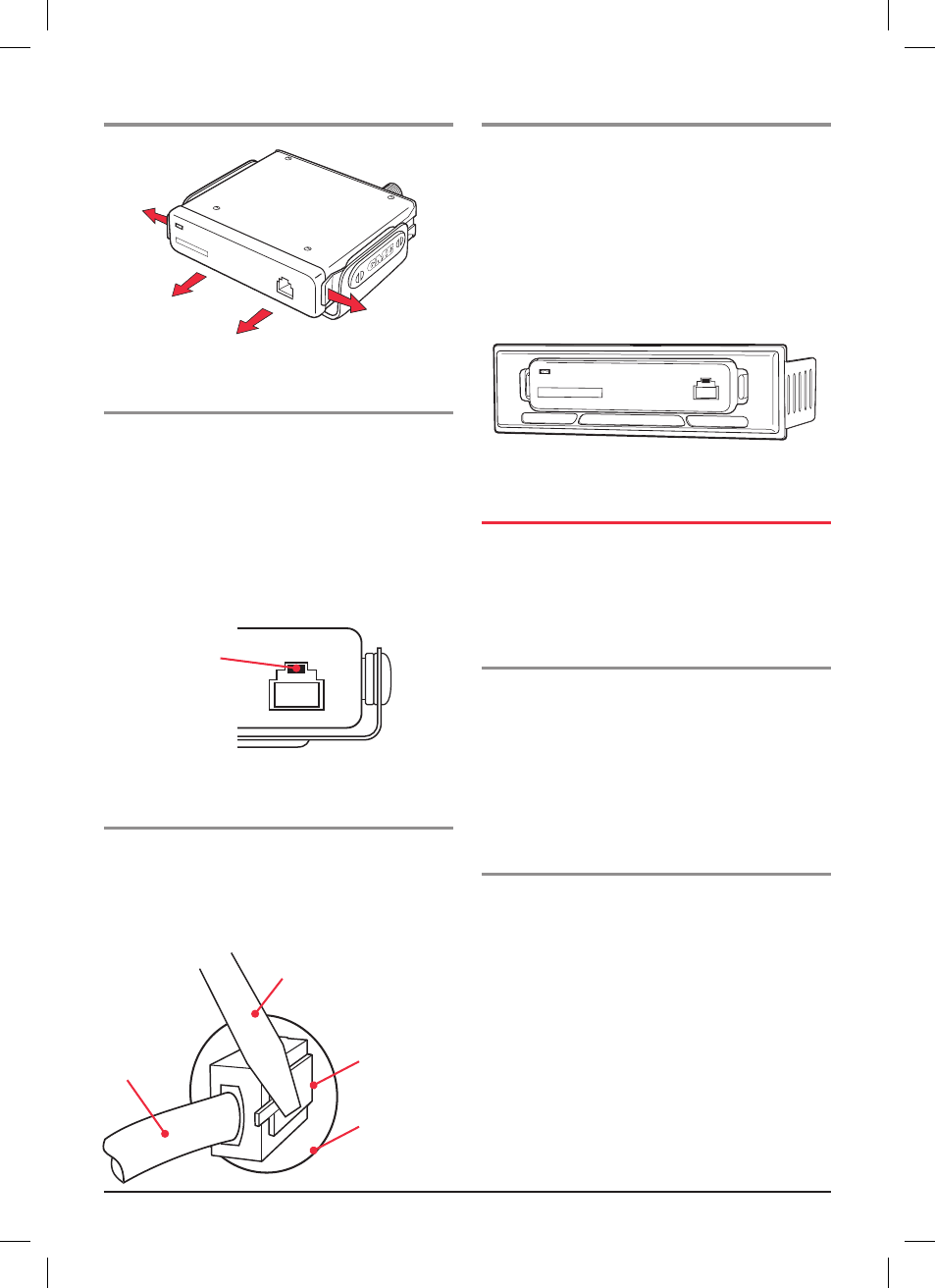
removing the radio
Fitting the microphone
the microphone uses an 8 pin plug and socket.
to fit the microphone:
1. Position the microphone plug so the plastic tab faces
downwards, and press the plug into the socket until
it ‘clicks’.
. Gently slide the rubber strain relief towards the
hole surrounding the socket until it is flush with
the front panel.
removing the microphone
1. slide the strain relief back along the microphone cord.
. squeeze the plastic tab on the microphone plug towards
the plug to unlock it while gently pulling the plug
outwards. if the plug does not come out easily, the
tab has not released correctly and should be
squeezed again.
console mounting the tx3440
For console mounting, a flush mounting Din Adaptor
mBD001 is available as an optional accessory. the adaptor
includes mounting brackets and a specially designed
front panel escutcheon to suit most vehicle installations.
the console mount is particularly suitable for dashboard
mounting tX3440’s main unit. installation instructions are
provided with the bracket. see your nearest GmE retailer
for details.
Dc poWEr connEction
the tX3440 is designed for 13.8 Volts Dc, negative earth
installations only (i.e. where the negative terminal of the
battery is connected to the chassis or frame of the vehicle).
there are two recommended methods of installation.
radio remains on when
the ignition switch is oFF
connect the radio's negative (black) lead to the vehicle's
chassis, or if preferred, directly to the battery's
negative terminal.
the radio's positive (red) lead should be connected via the
Amp fuse to the battery's positive terminal. Alternatively,
the positive lead could be connected into the fuse box at
a point that has +13.8 Volts continuously available (the
battery side of the ignition switch) via the Amp fuse.
radio turns oFF with the ignition switch:
connect the radio's negative (black) lead to the vehicle's
chassis, or if preferred, directly to the battery's
negative terminal.
the radio's positive (red) lead should connect to an
accessory point in the vehicle's fuse box via the Amp fuse.
this point should supply +13.8 Volts only when the ignition
switch is turned on or in the AccEssorY position.
cable
screwdriver
locking lever
move to left to
release Plug
cable entry hole
Gently
spread
tabs
slide radio
from cradle
Gently
spread
tabs
Plastic tab
UHF RADIO
UH
F R
AD
IO