GME TX3420 User Manual
Page 20
PA G E 2 0
i n s t r u c t i o n m A n uA l
t X 3 4 2 0
coNVertiNg the tx3420
iNto aN uNDerDash raDio
if your installation does not require the use of a remotely
mounted control head, you can convert your tX3420 to a
compact underdash radio by fitting the remote head front
panel directly to the main unit as follows .
remote head unit Disassembly
1 . remove the two black screws from the metal cable-
clamp plate at the rear of the remote unit .
2 . remove the 4 screws from the remote unit’s rear case
and remove the case .
3 . slide the rear case down the connecting cable and
carefully unplug the cable from the Pcb .
main unit Disassemble.
1 . remove the top and bottom covers from the main unit .
2 . Pull the dummy front panel away from the chassis and
carefully unplug the connecting cable .
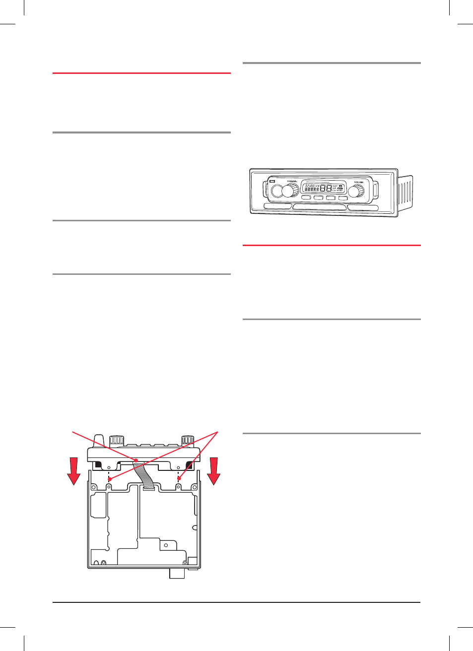
reassembly
1 . Plug the connecting cable from the main unit into the
remote head front panel .
2 . the remote front panel can be oriented so that the
speaker in the main unit is facing either up or down .
Position the front panel as required and slide it onto the
main chassis . if the front panel is oriented so the speaker
is facing uP, ensure the connecting cable is not crushed
between the front panel Pcb and the chassis . Align the
holes in the top and bottom of the plastic front panel
with the case screw holes in the chassis .
3 . refit the top and bottom covers and install the
cover screws .
console mounting the tx3420
for console mounting, a flush mounting din Adaptor
mbd001 is available as an optional accessory . the adaptor
includes mounting brackets and a specially designed
front panel escutcheon to suit most vehicle installations .
the console mount is particularly suitable for dashboard
mounting tX3420’s that have been converted from remote
units to under-dash units (as described above) . installation
instructions are provided with the bracket . see your nearest
GmE retailer for details .
Dc PoWer coNNectioN
the tX3420 is designed for 13 .8 Volt dc, negative earth
installations only (i .e . where the negative terminal of the
battery is connected to the chassis or frame of the vehicle) .
there are two recommended methods of installation .
radio remains oN when
the ignition switch is oFF
connect the radio's negative (black) lead to the vehicle's
chassis, or if preferred, directly to the battery's
negative terminal .
the radio's positive (red) lead should be connected via the
2 Amp fuse to the battery's positive terminal . Alternatively,
the positive lead could be connected into the fuse box
at a point that has +13 .8 Volts continuously available
(preferably the battery side of the ignition switch) via
the 2 Amp fuse .
radio turns oFF with the ignition switch
connect the radio's negative (black) lead to the vehicle's
chassis, or if preferred, directly to the battery's
negative terminal .
the radio's positive (red) lead should connect to an
accessory point in the vehicle's fuse box via the 2 Amp fuse .
this point should supply +13 .8 Volts only when the ignition
switch is turned on or in the AccEssory position .
connect plug
Align holes
T X 3 4 2 0