Installation, Installing the din mount, Dc power connections – GME TX2720 User Manual
Page 8
PAGE 8
INSTRUCTION MANUAL
TX2720
INSTALLATION
The TX2720 is supplied with a DIN mounting
bracket for mounting into a standard DIN sized
cavity in the vehicle’s console or dashboard.
Before installing the radio, ensure the DC cable
and antenna have been installed correctly (as
described further below) and the connectors are
accessible through the DIN cavity.
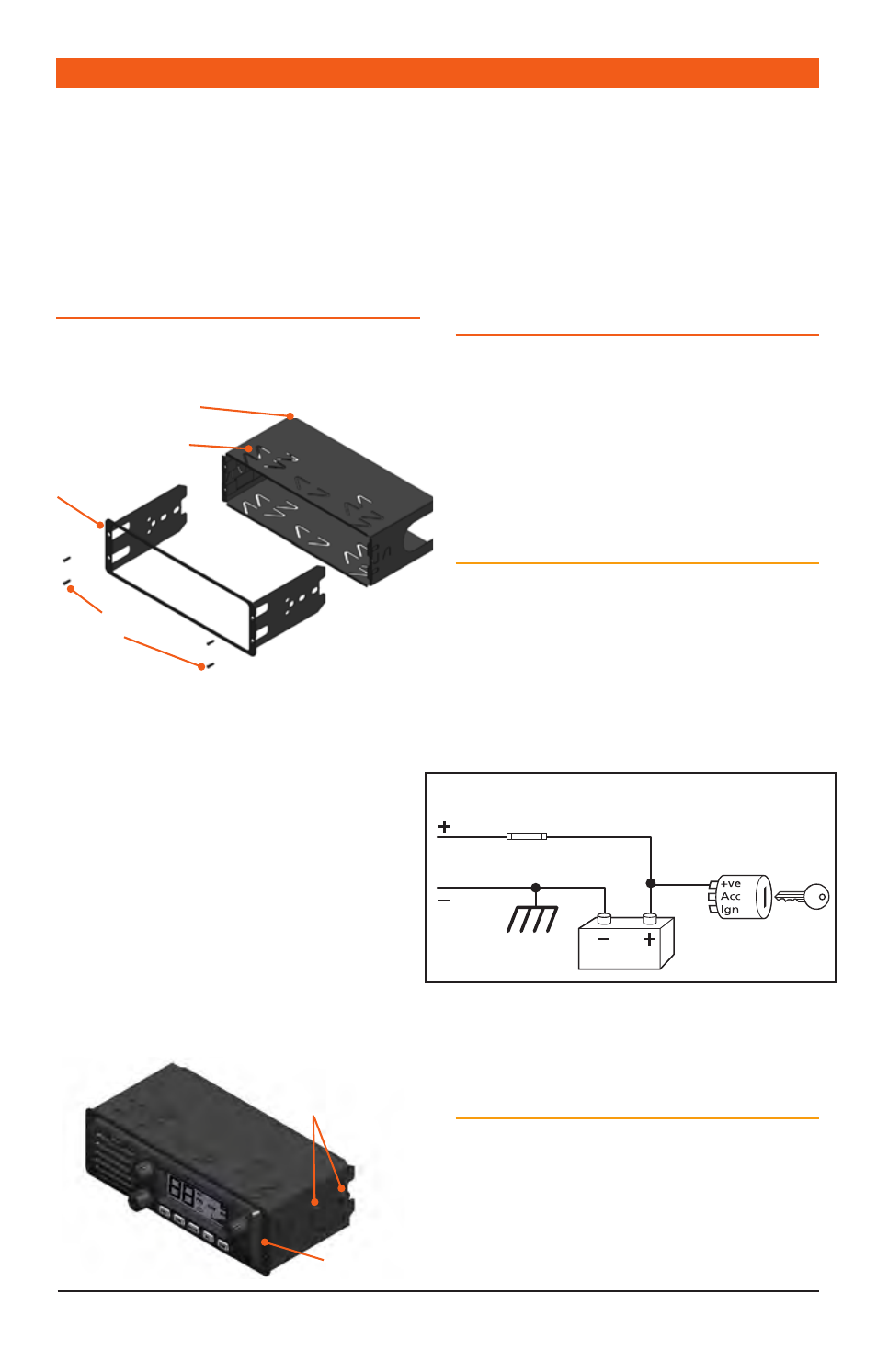
INSTALLING THE DIN MOUNT
To install the DIN mount you will need access to
the rear of the vehicle’s console.
1. Remove the four small front mounting bolts
from the front edges of the DIN mount
and separate the front frame from the DIN
surround.
2. Slide the DIN surround into the DIN slot in the
vehicle’s console and secure it in the desired
position by bending the folding tabs.
3. Slide the TX2720 radio into the front frame so
that the threaded holes in the chassis line up
with the holes in the front frame.
4. Secure the radio using the four 8 mm bolts
and washers provided.
5. Connect the DC connector and PL259 antenna
(and rear microphone extension lead if used)
to the sockets on the radio’s rear panel.
6. Slide the front frame back into the DIN
surround and secure it using the four small
front mounting bolts.
You can now refit the console to the vehicle.
DC POWER CONNECTIONS
The TX2720 is designed for 13.8 V DC negative
earth installations only (i.e. where the negative
side of the battery is connected to the frame
or chassis of the vehicle). There are two
recommended methods of installation. Please
refer to the following diagrams.
Radio remains On when the Ignition
switch is Off
Connect the radio’s negative (Black) lead to
the vehicle’s chassis or if preferred directly to
the battery’s negative terminal. Connect the
radio’s positive (Red) lead, via the 2 amp fuse,
to the battery’s positive terminal or to a point in
the fuse box that has +13.8 volts continuously
available.
The radio can now be switched ON or OFF at any
time using the switch on the volume control.
Radio Turns On and Off with the Ignition
switch
Connect the radio’s negative (Black) lead to the
vehicle’s chassis or if preferred directly to the
battery’s negative terminal. Connect the radio’s
positive (Red) lead, via the 2 amp fuse, to the
accessory point in the fuse box. This point should
Radio remains ON when ignition switch is OFF
RED
Fuse
Fuse
BLACK
Chassis
Car battery
Ingnition Switch
Radio turns ON and OFF with ignition switch
RED
BLACK
Chassis
Car battery
Ingnition Switch
To Radio
To Radio
DIN Surround
Folding Tabs
Front Mounting
Bolts
Front Frame
8 mm Bolts
and Washers
Front Frame