Instructions for use @) – Philips VSS9451 User Manual
Page 5
Attention! The text in this document has been recognized automatically. To view the original document, you can use the "Original mode".
INSTRUCTIONS FOR USE @)
CONNECTIONS
TECHNICAL DATA
-€» O
76û H.gh
\
J
a. Electrical
Picture tube:.................................. 14°, 90° deflection, 0.42 mm
Resolution:................................. > 520 TVL (bandwith 6.5 MHz)
Signal inputs:
- CVBS:.................................... 1 Vpp into 75 Q or bridging/BNC
- Y/C:...................1 Vpp/300mVpp into 75 Q/Hosiden {MINI DIN)
-Audio:.................................................................... 177mVeff into 10 K Ì2
TV standard:..............................................PAL, 625 lines, 50 Hz
Power supply:...................mains voltage 198 -264 V AC / 50 Hz
b. Environmental
Temperature range:...........................operating: + 10 to + 40° C
............................................................. storage: - 25 to + 70° C
Humidity:...................................... 20% - 95% (non condensing)
s:
_<2
"o)
c
HI
Subject to modification.
1 POWER
• Connect to the mains socket using the mains lead supplied.
2 CVBS
•© - Input socket for composite video signal.
• Connect to e.g. a video camera, VCR or video control panel.
G» - Output socket for signal loopthrough to other equipment.
• Connect to e.g. a second monitor or VCR.
3 Audio
■© - Input socket for audio signal.
• Connect to e.g. an audio control panel or amplifier.
G» - Output socket for signal loopthrough to other equipment.
• Connect to e.g. a second monitor or VCR.
4 75 0-High
Signal line termination switch for CVBS in- outputs.
• Switch to 75 O when there is only input signal.
• Switch to High in case of loopthrough operation.
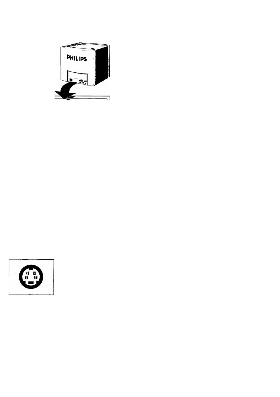
5 Y/C Input
Input socket for luminance (Y) and chrominance (C) signal.
This input can be used in applications where high resolution
is required.
Socket and signals according to S-VHS standard.
1 GND (luminance)
2 GND (chrominance)
3 LUMINANCE signal
4 CHROMINANCE signal
6 Notch Off
To avoid cross colour interference when using the CVBS
input (2).
In high resolution Y/C operation this switch should preferably
be set to off.
NOTE!
Never use the CVBS (2) and the Y/C (5) connection at the
same time.