Operating instructions, Audio i/o connection, Operating modes – Fredenstein U70F User Manual
Page 4
Fredenstein U70F Peak Programme Meter
Operating Instructions:
The On/Off switch is located on the back‐panel close to the AC inlet. After turning the
U70F on, the instrument will go through a test and calibration cycle. First a single dot will
ascend and then invert and descend. The illumination of the 10 green LEDs will indicate
the successful completion of this cycle and the instrument is then ready for normal
operation.
A failure of the self‐test and/or the calibration will be light the 10 red LEDs. In this
case the instrument will need to be repaired by Fredenstein or an authorized service
epresentative. Do not open yourself the U70F, high voltage is present inside and can lead to a
otentially fatal electric shock.
r
p
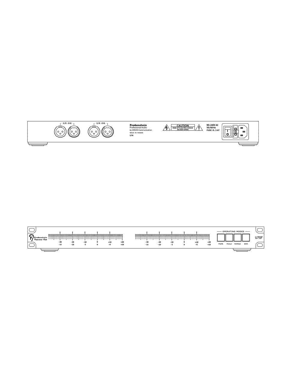
Audio I/O Connection
Fig. 1 Back view of U70F
There are two audio I/O channels of U70F. Each channel features an XLR balanced input
and output to simplify the insertion of the U70F between the source and the destination
equipment.
Standard calibration is +4 dBu (1.23V sine‐wave at 1 kHz) for a 0 dB meter reading. The
70F is a PPM calibrated in RMS values. Other calibration levels are available at the time
f ordering.
U
o
Operating Modes
Fig. 2 Front view of U70F
The four illum
front‐panel determine
the operating
inated push button switches on the right side of the
PEAK
modes (labeled PEAK, HOLD, RANGE, and BAR)
:
Engages the Peak Hold mode with a 2.5s hold time
HOLD:
Engages the Peak Hold mode with manual reset. To reset the peak value
simply release the switch and engage it again.
RANGE:
Fredenstein U70F Manual V2.1 July 16, 2014 Page 3
Engages: the high resolution meter range of ‐19.5 to +10 dB (0.5 dB/step), if
not engaged the range is ‐39 dB to +20 dB (1 dB/step).
BAR:
Engages the bar display mode, if not engaged the dot mode is selected (like a
traditional U70)