Receiving instructions, Mounting, Nomenclature – FloAire DX COIL User Manual
Page 2
EVAPORATOR IOM
Guidelines for the installation, operation and maintenance of Heatcraft’s direct expansion (DX)
cooling coils have been provided to help insure proper performance of the coils and their longevity.
These are general guidelines that may have to be tailored to meet the specific requirements of any
one job. As always, a qualified party or individual should perform the installation and maintenance
of any coil. Protective equipment such as safety glasses, steel toe boots and gloves are recommended
during the installation and routine maintenance of the coil.
Receiving Instructions
1. All Heatcraft coils are factory tested, inspected and carefully packaged.
2. Damage to the coils can occur after they have left the factory. Therefore, the coils should
be inspected for shipping damage upon receipt. The freight bill should also be checked
against items received for complete delivery.
3. Damaged and/or missing items should be noted on the carrier’s freight bill and signed by
the driver.
4. For additional assistance, contact your local Heatcraft representative.
Mounting
1. Position the coil such that the suction header is at the entering air-side of the coil and the
distributor tubes are at the leaving air-side of the coil. This orientation provides counter-
flow heat exchange which is required for proper coil performance.
2. The suction connection is located at the bottom of the coil when properly installed.
3. See Figure 1 - Evaporator Coils.
1
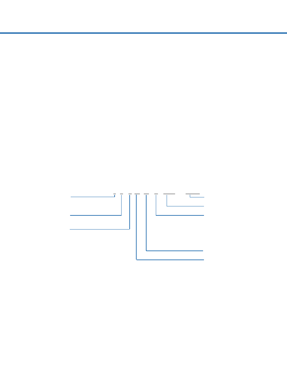
5 E N 14 06 C 24.00 x 144.00
Tube O.D.
Finned Length (inches)
4=1/2”
5=5/8”
Fin Height (inches)
Coil Type
Fin Design
E = Evaporator
A - flat (Al, Cu)
B - corrugated (Al, Cu)
Circuiting
C - sine wave (Al, Cu)
N = Normal
F - flat (SS, CS, Al, Cu)
F = Face Control
G - corrugated (SS, CS, Al, Cu)
R = Row Control
H - sine wave (SS, CS, Al, Cu)
J = Interlaced
K = Interlaced Face Control
Rows Deep
Fins Per Inch
Nomenclature