Component description, Variable frequency drive, Ecpm03 board – FloAire Demand Control Ventilation System User Manual
Page 28
A0023662
May 2014 Rev.5
28
Component Description
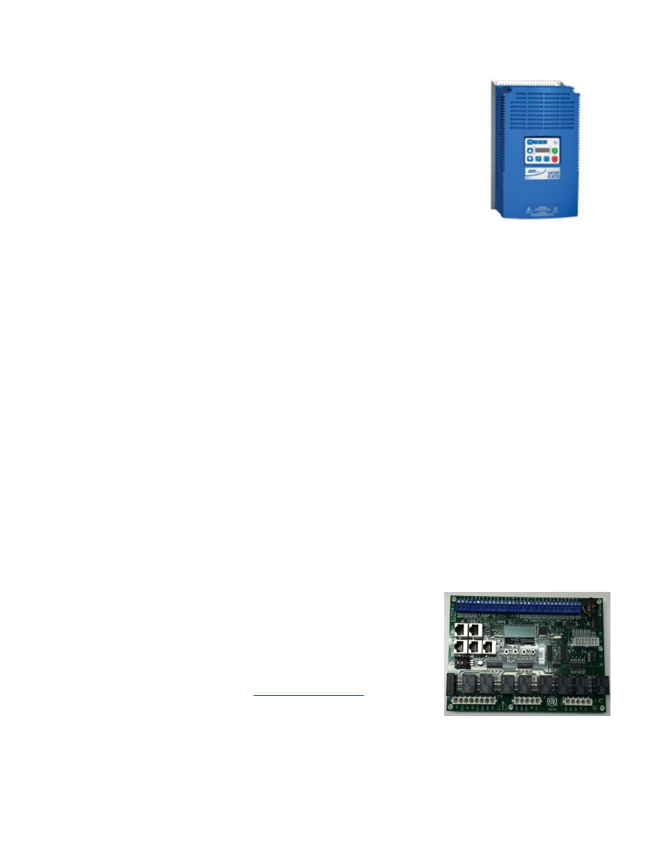
Variable Frequency Drive
Variable frequency drives change the speed of 3 phase motors by changing the
frequency signal sent to the motor. There is one variable frequency drive for each
fan in this system. 2 RJ-45 plugs are used to connect the drives to each other and
to the ECPM03 controller through CAT-5 cables.
Variable Frequency Drive Parameters
Variable frequency drive parameters can be changed with the buttons on the face
of the drive. Only parameters P107 (Line voltage Selection) and P108 (Motor
Overload) should be adjusted in the field if needed. All other settings can be adjusted through the HMI.
P107 is set to 0 (Low) if motor voltage is 120 VAC, 208 VAC or 400 VAC. P107 is set to 1 (High) if motor
voltage is 230 VAC, 480 VAC or 575 VAC.
P108 is calculated as Motor FLA x 100 / Drive Output Rating (available in the VFD cross reference table
under the Electrical Installation chapter above).
To enter the PROGRAM mode to access the parameters:
1. Press the Mode (M) button.
2. If no password
is required, the display will read “P100”. If it prompts for a password (PASS), use
the Up and Down buttons to scroll to the password value (the factory default password is “0225”)
and press the Mode (M) button. Once the correct password is entered, the display will read
“P100”, which indicates that the PROGRAM mode has been accessed at the beginning of the
parameter menu.
3. Use the Up and Down buttons to scroll to the desired parameter number.
4. Once the desired parameter is found, press the Mode (M) button to display the present parameter
setting. The parameter value will begin blinking, indicating that the present parameter setting is
being displayed. The value of the parameter can be changed by using the Up and Down buttons.
5. Pressing the Mode (M) button will store the new setting and also exit the PROGRAM mode. To
change another parameter, press the Mode (M) button again to re-enter the PROGRAM mode. If
the Mode button is pressed within 1 minute of exiting the PROGRAM mode, the password is not
required to access the parameters. After one minute, the password must be re-entered in order to
access the parameters again.
P500 parameter provides a history of the last 8 faults on the drive. It can be accessed without getting into
PROGRAM mode.
ECPM03 board
The ECPM03 is the main brain of the system. It receives all the digital and
analog inputs and delivers the digital outputs and sends out messages to
other devices.
Connector Descriptions
J1, J2: Modbus slave network connectors feed through RJ45s,
which conform to the Modbus pin out for RS485 2 wire differential
Modbus RTU standard. Se
Modbus
communication is not configured for third party integration without
additional components.
J3, J4, J5: Modbus master network connectors, feed through RJ45s, which conform to the
Modbus pin out for RS485 2 wire differential Modbus RTU standard. J4 and J5 are the only RJ45
port on the ECPM03, which serves as a power source for HMI(s).
J6: Factory low voltage connections