2 load cell connection, 3 analogue output connection – Flintec FAA-26 User Manual
Page 9
FAA-26, Technical Manual, Rev. 1.1, June 2014
Page 8 / 13
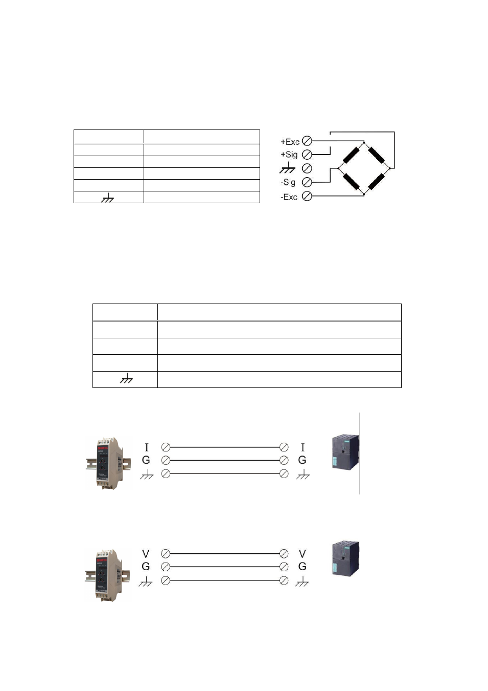
4.2 Load Cell Connection
The load cell wiring should be made carefully before energizing to avoid damages to
the instrument and load cells. The input resistance of the load cells that you want to
connect should be more than 85 Ω.
Pin Name
Load Cell Cable
+Ex
+ Excitation
-Ex
- Excitation
+Si
+ Signal
-Si
- Signal
Shield
4.3 Analogue Output Connection
Only one of the analog output types can be used at the same time and has to be
selected in the setup. Install the analog output measuring instrument for adjustment,
if need be.
Pin Name
Definition
I
Current Output
V
Voltage Output
G
GND
Shield
Current output connection
Voltage output connection