Front view, features and specifications – Flintec FAA-26 User Manual
Page 5
FAA-26, Technical Manual, Rev. 1.1, June 2014
Page 4 / 13
3.
Front View, Features and Specifications
Microcontroller based analog load cell transmitter FAA-26 has very high accuracy
and long term stability with its high tech design.
This high accurate instrument gives the system designers a lot of advantages to
increase the system reliability and to reduce the installation and service times. All
instrument
s’ analog outputs are matched in the production to perform calibration at
PLC and for changing the instrument without recalibration in service if adjustment is
done in PLC.
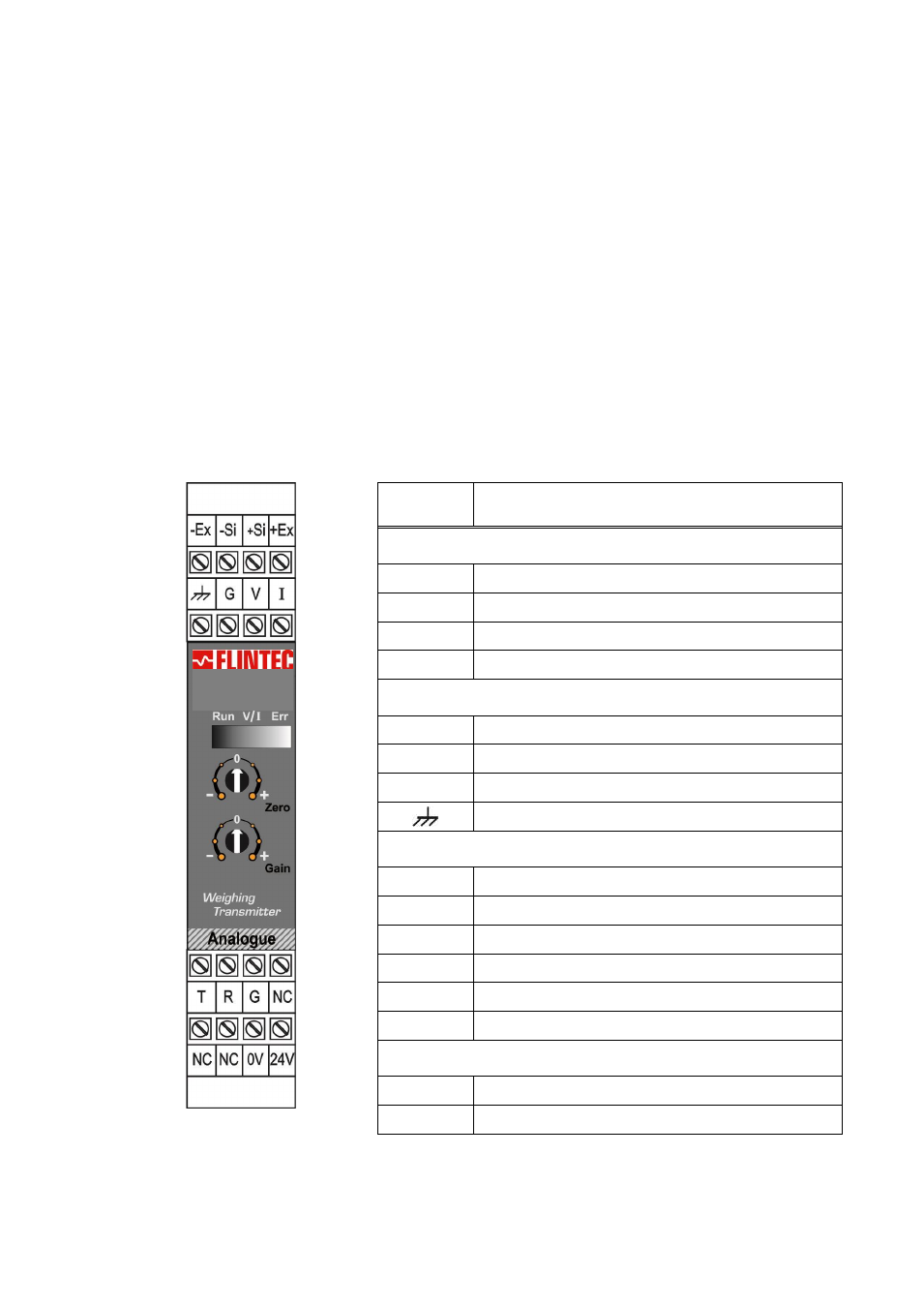
There are 2
rotary switches and annunciator LED’s in front of the instrument.
The upper rotary switch adjusts
unloaded scale’s analog output level (zero
adjustment) and the lower rotary switch adjusts gain of the instrument. The front view
and pin descriptions of FAA-26 is shown below.
Pin
Name
Definition
LOAD CELL CONNECTION
- Ex
- Excitation
+ Ex
+ Excitation
- Si
- Signal
+ Si
+ Signal
ANALOGUE OUTPUT
I
4 - 20mA output
V
0 - 10V output
G
GND
Shield and Protective ground
ANALOG OUTPUT RANGE
T
Refer to chapter 4.4
R
Refer to chapter 4.4
G
Ground
NC
Not used
NC
Not used
NC
Not used
POWER SUPPLY
24V
+24VDC
0V
0VDC
FAA-26