Adjustments 5.1 adjustment with rotary switch – Flintec FAA-26 User Manual
Page 11
FAA-26, Technical Manual, Rev. 1.1, June 2014
Page 10 / 13
5. Adjustments
5.1 Adjustment with rotary switch
Zero and Gain adjustment rotary switches are used to adjust zero and gain of the
analog output. Both switches must be at
“0“ positions when the adjustment starts.
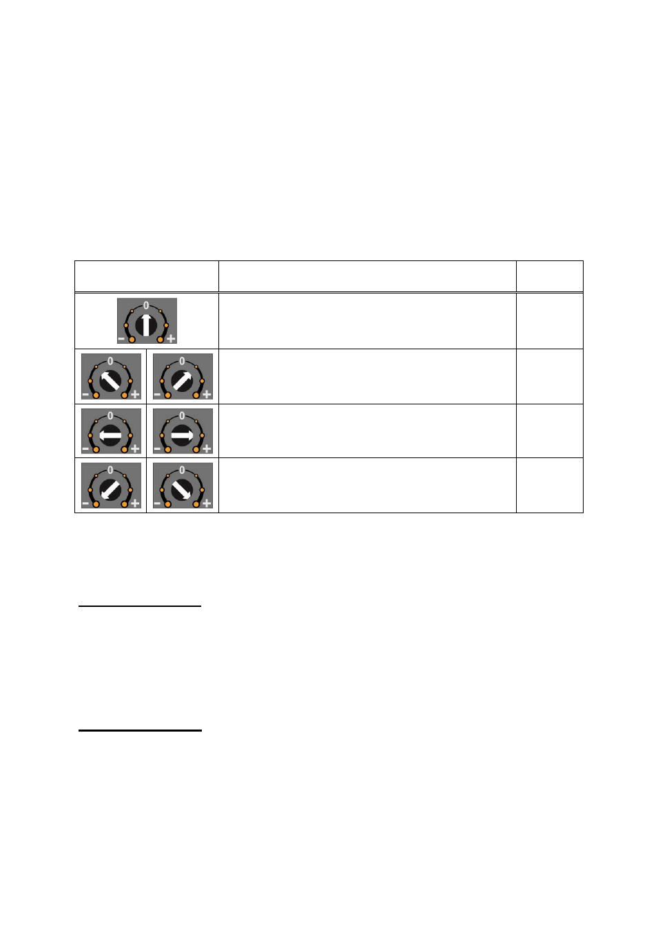
Adjustment is done by turning the adjustment switch as described in the table below.
Adjustment rotary
switch position
Rotary switch description
Run
LED
Operation, No any change,
On
Decrease ( - ) / Increase ( + ) in slow steps
Flash
Decrease ( - ) / Increase ( + ) in medium steps
Flash
Decrease ( - ) / Increase ( + ) in big steps
Flash
RUN LED flashes to indicate the instrument is in adjustment mode.
Zero Adjustment
- Connect the measurement instrument to the analog output.
- Unload the scale.
- Increase or decrease the analog output by zero adjustment rotary
switch.
- The zero adjustment rotary switch should be at
“0“ position at the end of
the adjustment.
Gain Adjustment
- Connect the measurement instrument to the analog output.
- Load the scale.
- The analog output value should be calculated for the applied load.