Operating instructions – ebm-papst G3G250-MW50-01 User Manual
Page 8
Operating instructions
G3G250-MW50-01
Translation of the original operating instructions
DANGER
Electrical load (>50 µC) between mains wire and
protective earth connection after switching of the supply
when switching multiple devices in parallel.
Electric shock, risk of injury
→ Make sure that sufficient protection against accidental contact
is provided.
Before working on the electrical connection, the
connections to the mains supply and PE must be shorted.
CAUTION
Electrical voltage
The device is a built-in component and features no electrically
isolating switch.
→ Connect the device only to circuits that can be switched off
using an all-pole disconnecting switch.
→ When working on the device, you must switch off the
system/machine in which the device is installed and secure
it from being switched on again.
NOTE
Interferences and failures are possible
Maintain a distance to the power supply line when routing the
control lines of the device.
→ Ensure a sufficiently large clearance.
Recommendation: clearance > 10 cm (separate cable
routing)
NOTE
Water penetration into leads or wires
Water enters at the cable end on the customers side and can
damage the device.
→ Make sure that the cable end is connected in a dry
environment.
The control voltage circuit is not electrically isolated. Connect
the device only to circuits that can be switched off using an all-
pole disconnecting switch.
4.2.1 Prerequisites
; Check whether the data on the type plate agree with the connection
data.
; Before connecting the device, ensure that the supply voltage matches
the operating voltage of the device.
; Only use cables designed for current according to the type plate.
For determining the cross-section, follow the basic principles in
accordance with EN 61800-5-1. The protective earth must have a
cross-section equal to or greater than the outer conductor cross-
section.
We recommend the use of 105°C cables. Ensure that the minimum
cable cross-section is at least
AWG26/0.13 mm².
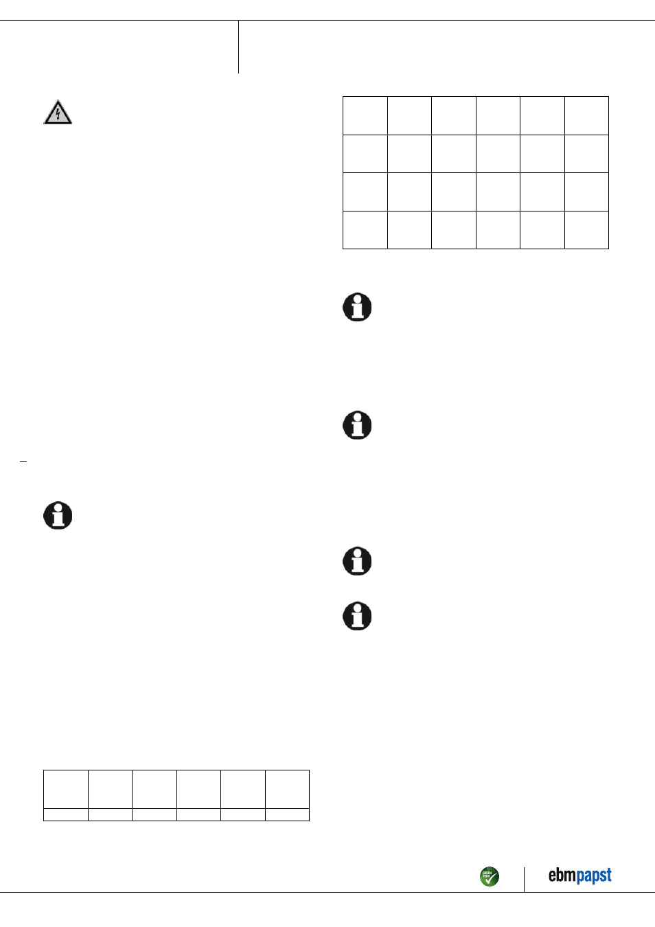
4.2.2 Power supply connection, fuse protection
Assignment of conductor cross-sections and the fuse protection required
for them (overload protection only, no device protection).
Nominal
voltage
Safety
fuse
Automatic
circuit
breaker
Wire
cross-
section
Wire
cross-
section
VDE
UL
VDE
mm²
*AWG
3/PE AC
380 - 480
VAC
16 A
15 A
C16A
1.5
16
3/PE AC
380 - 480
VAC
20 A
20 A
C20A
2.5
14
3/PE AC
380 - 480
VAC
25 A
25 A
C25A
4.0
12
3/PE AC
380 - 480
VAC
32 A
30 A
C32A
6.0
10
* AWG = American Wire Gauge
4.2.3 Idle current
Because of the EMC filter integrated for compliance with EMC
limits (interference emission and interference immunity), idle
currents in the mains cable can be measured even when the
motor is at a standstill and the mains voltage is switched on.
●
The values lie in a range of typical < 250 mA.
●
The effective power in this operating state (readiness for operation) is
simultaneously at typical < 5 W.
4.2.4 Residual current operated device
Only universal (type B or B+) RCD protective devices are
permitted. Like frequency inverters, RCD protective devices
cannot provide personal safety while operating the device.
When switching on the power supply of the device, pulsed
charge currents from the capacitors in the integrated EMC filter
can lead to the RCD protective devices triggering without
delay. We recommend residual current devices with a trigger
threshold of 300 mA and delayed triggering (super-resistant,
characteristic K).
4.2.5 Leakage current
For asymmetrical power systems or if a phase fails, the
leakage current can increase to a multiple of the nominal value.
4.2.6 Locked-rotor protection
Due to the locked-rotor protection, the start-up current (LRA) is
equal to or less than the nominal current (FLA).
4.3 Connection in terminal box
4.3.1 Preparing connection lines for the connection
Strip the cable just enough so that the screwed cable gland is tight and
the terminals are relieved of strain. Tightening torque, see chapter 3.1
Product drawing.
Item no. 50734-5-9970 · Revision 82547 · Release 2014-05-08 · Page 8 / 14
ebm-papst Mulfingen GmbH & Co. KG · Bachmühle 2 · D-74673 Mulfingen · Phone +49 (0) 7938 81-0 · Fax +49 (0) 7938 81-110 · [email protected] · www.ebmpapst.com