Integrated remote powering options diagram, Tps link modes, Tps cat-x power cable power send – DVIGear DVI-TPS-RX95-HD User Manual
Page 8: 12v 3a dc in, 12v 4a dc in, Dvi-tps-rx95-hd no power send disabled (local), 12v dc power adapter
8
DVIGear
1059 Triad Court, Suite 8,
Marietta, GA 30062
Toll Free: 888.463.9927
Tel: 770.421.6699
Fax: 770.234.4207
[email protected]
www.dvigear.com
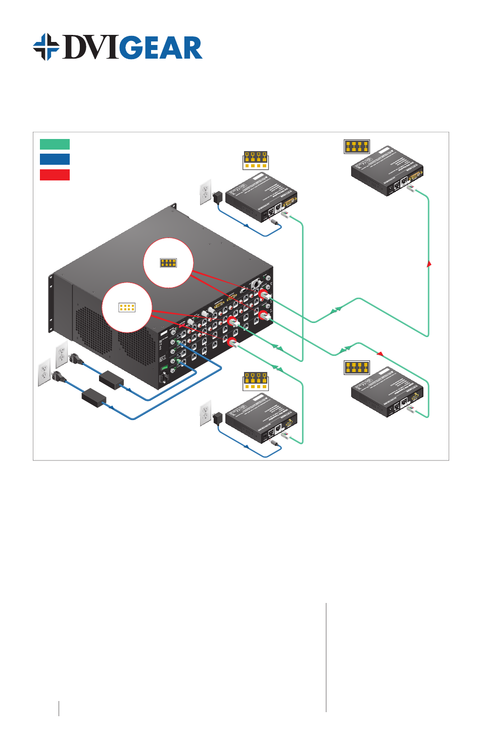
Integrated Remote Powering Options Diagram
Please see the remote power sections on pages 4 and 7 for instructions on configuring remote power.
MX-T
PS-IB-S
12V
3A
DC IN
8 CH
TPS INPUT
BOARD
12V p
ower o
n TPS co
nnecto
r. On
ly u
se with
comp
atib
le d
evices!
TP
S IN 1 TP
S IN 2 TP
S IN 3 TP
S IN 4 TP
S IN 5 TP
S IN 6 TP
S IN 7 TP
S IN 8
MX-T
PS-IB-S
12V
3A
DC IN
8 CH
TPS IN
PUT
BOA
RD
12V p
ower o
n TPS co
nnecto
r. On
ly u
se with
comp
atib
le d
evices!
TP
S IN 1 TP
S IN 2 TP
S IN 3 TP
S IN 4 TP
S IN 5 TP
S IN 6 TP
S IN 7 TP
S IN 8
MX-T
PS-OB-S
12V
4A
DC IN
8 CH
TPS OUT
PUT
BOAR
D WIT
H D
IGIT
AL
AUDIO
12V p
ower o
n TPS co
nnecto
r. On
ly u
se with
comp
atib
le d
evices!
TPS
OUT 1 TP
S O
UT 2
TP
S O
UT 3
TP
S O
UT 4 TP
S O
UT 5 TP
S O
UT 6 TP
S O
UT 7
TP
S O
UT 8
S/P
DIF I/O
1 S
/PDIF I/O
2 S
/PDIF I/O
3 S
/PDIF I/O
4 S
/PDIF I/O
5 S
/PDIF I/O
6 S
/PDIF I/O
7 S
/PDIF I/O
8
MX-T
PS-OB-S
12V
4A
DC
IN
8 CH
TPS OU
TPU
T BOA
RD WIT
H DIGIT
AL
AUD
IO
12V p
ower o
n TPS co
nnecto
r. On
ly u
se with
comp
atib
le d
evices!
TPS
OUT 1 TP
S O
UT 2
TP
S O
UT 3
TP
S O
UT 4 TP
S O
UT 5 TP
S O
UT 6 TP
S O
UT 7
TP
S O
UT 8
S/P
DIF I/O
1 S
/PDIF I/O
2 S
/PDIF I/O
3 S
/PDIF I/O
4 S
/PDIF I/O
5 S
/PDIF I/O
6 S
/PDIF I/O
7 S
/PDIF I/O
8
Enabled
Remote Power
Disabled
Remote Power
DVI-TPS-RX95-HD
Power Send
Enabled
TPS CAT-X
Power Cable
Power Send
12V DC
Power Adapter
DVI-TPS-TX95-HDMI
No Power
Send
Disabled
(local)
Power Send
DVI-TPS-TX95-HDMI
Enabled
12V DC
Power Adapter
DVI-TPS-RX95-HD
No Power
Send
Disabled
(local)
Maximum Cable Lengths Between MXP Series TPS Boards and Extenders
The maximum cable extension distances are the same as is mentioned in the table on page 5.
TPS Link Modes
If a TPS 95 Series extender is connected to a TPS I/O board, the matrix board will force the extender
to use the settings of the matrix switcher. In this case, the extender’s TPS mode switch has no effect.
For detailed information see the MXP Series User Manual.
DVI-TPS-TX95-HD_DVI-TPS-RX95-HD-QSG-01 / March.2014
HDBaseT™ and the HDBaseT Alliance logo are trademarks of the HDBaseT Alliance.