Installation, Audio connections – Drawmer 1962 Digital Vacuum Tube Pre-Amplifier User Manual
Page 8
1962 OPERATORS’ MANUAL
4
INSTALLATION
The 1962 is designed for standard 19" rack mounting and occupies 2U (88mm) of rack
space. Avoid mounting the unit directly above power amplifiers or power supplies that
radiate significant amounts of heat, or in poorly ventilated or unusually warm environments.
We advise that a blank space above the unit with a ventilated rack blanking panel is fitted.
Fibre or plastic washers may be used to prevent the front panel becoming marked by the
mounting bolts. In mobile systems, it is recommended that a shock resistant flight case is
used. In severe conditions where there might be excessive vibration, additional rear support
might be required.
AUDIO CONNECTIONS
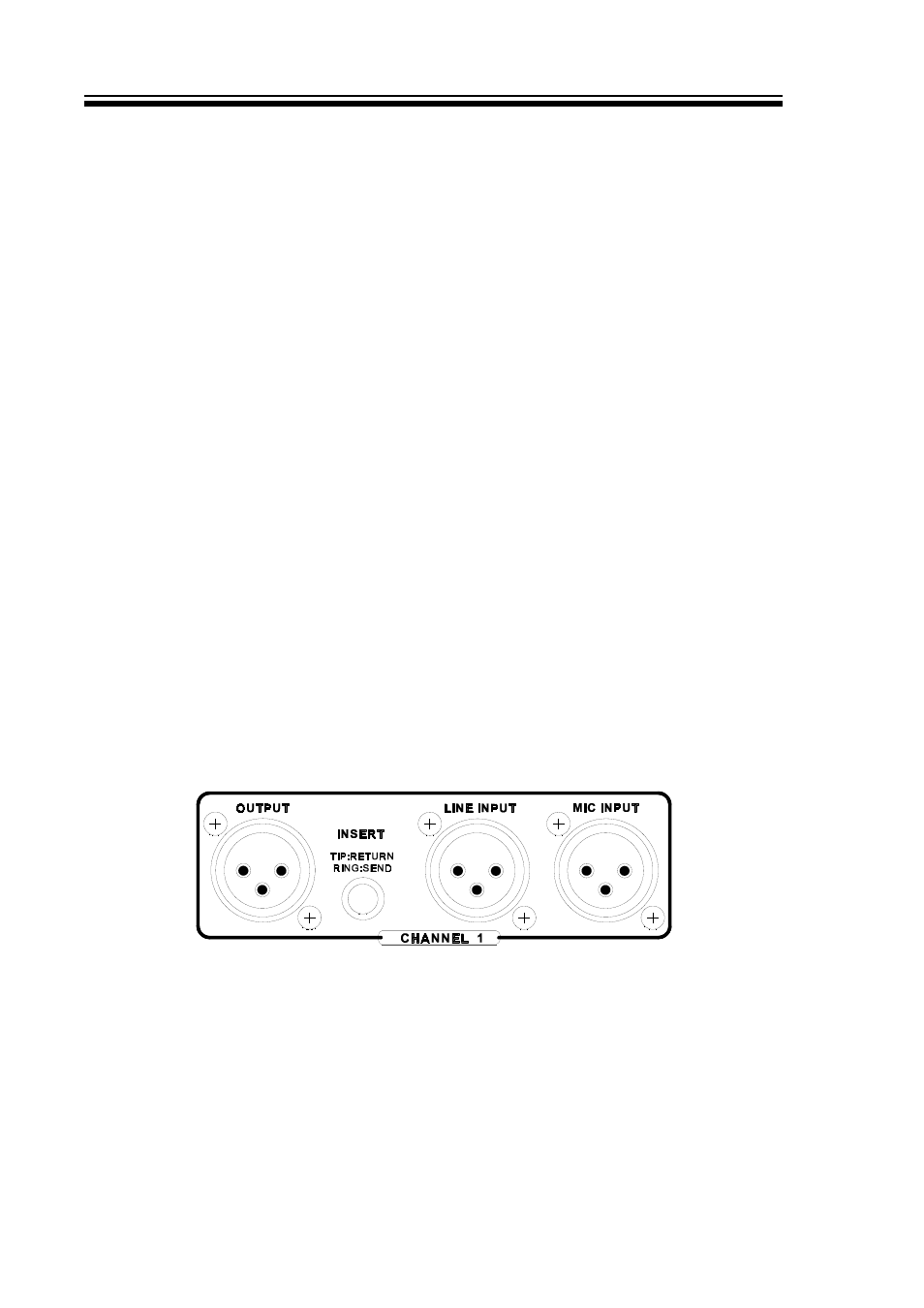
CHANNEL IN/OUT
The channel inputs and outputs are electronically balanced on conventionally wired XLRs
(pin1 screen, pin 2 hot, pin 3 cold and XLR shell is connected to the chassis), with an
operating level nominally of +4dBu. If the unit is to be used where it may be exposed to high
levels of disturbance (such as found close to a TV or radio transmitter), we suggest that the
screen of the signal cable be connected to the chassis connection on the XLR connector as
opposed to connecting to pin1. The 1962 fully conforms to the EMC standards.
If ground loop problems are encountered, never disconnect the power inlet earth, but
instead, try disconnecting the signal screen on one end of each cable connecting the
outputs of the 1962 to the patchbay. If such measures are necessary, balanced operation
is recommended. Various signal cable earthing options may have to be tried to achieve the
most hum-free connection.
The intended use of the audio insert jacks would be to patch in an additional EQ (eg
Drawmer 1961), reverb or similar processing to the signal path. Insert connection is via
quarter-inch TRS jacks, the wiring convention being: ring - signal send, tip - signal return
and sleeve - ground. The insert jack may be permanently wired to a normalised patch bay
for easier connection. The signal path to and from this insert jack and enhance any external
processing can be overridden by disabling the Fine EQ section.
STEREO OUTPUTS
The Stereo Mix Output XLRs are electronically balanced and follow the usual wiring
convention of: pin 1 screen, pin 2 hot, pin 3 cold and XLR shell connected to the chassis.
If the unit is to be used where it may be exposed to high levels of disturbance (such as close
to a TV or radio transmitter), we suggest that the screen of the signal cable be connected
to the chassis connection on the XLR connector as opposed to connecting to pin1. The 1962
fully conforms to the EMC standards.
If ground loop problems are encountered, never disconnect the power inlet earth, but
instead, try disconnecting the signal screen on one end of each cable connecting the