Chapter 1, Installation, Power connection – Drawmer SL22 Sound Level Limiter User Manual
Page 3
3
CHAPTER 1
(or before the active speakers), with the amplifier volume
set to maximum. If the SL22 were to be connected earlier
in the chain, prior to the pre-amp/mixer for example, then
it would be possible to add gain, sending noise levels
higher than required.
The SL22 can be used in a configuration where a stereo
output is distributed around several speakers. Fig.3 shows
a setup where the signal is distributed into six pairs using
a Drawmer DA6, whilst still providing speaker protection
for all twelve speakers. Again, note the position of the
SL22’s along the audio chain - they should all be
connected directly before the amplifier that is supplying
the speakers (or active speakers), with the amplifier
volume set to maximum.
INSTALLATION
The SL22 Sound Level Limiter is designed for standard
19" rack mounting and occupies 1U of rack space. Where
possible, avoid mounting the unit directly above power
amplifiers or power supplies that radiate significant
amounts of heat.
If the unit is to be used in a mobile situation, it is strongly
recommended that the rear of the unit is supported in the
carrying rack to avoid bending the front panel rack
mounting ‘ears’. Use fibre or plastic washers to prevent
the front panel becoming marked by the mounting bolts.
Always connect the mains earth to the unit.
Fig. 2 shows the ideal connection setup, providing the
greatest protection for your system. Note the position of
the SL22 along the audio chain - it should be connected
directly before the amplifier that is supplying the speakers,
POWER CONNECTION
The SL22 unit will be supplied with a power cable suitable for domestic power outlets in your country. For your own
safety, it is important that you use this cable to connect to the mains supply earth. The cable must not be tampered
with or modified.
The SL22 has an internal fuse to suit the mains voltage for which the unit has been supplied. The fuse should never
blow under normal operation. If the fuse is suspected of having blown, then a fault will have occurred and this fault
condition should be inspected by a qualified service engineer. When replacing the fuse, always comply with the
Safety Instructions.
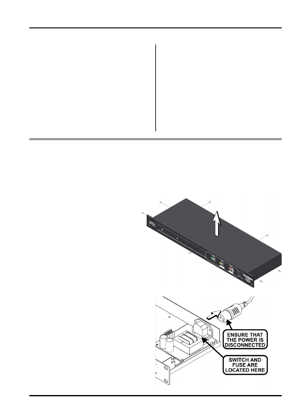
If the unit is to be used with a mains input operating
voltage different to that for which the unit is supplied,
the following procedure must be carried out by a
technically competent person:
1: Disconnect the unit from the mains.
2: Using a number 1 size pozidrive screwdriver,
remove the seven self-tapping screws that retain
the top cover. Two screws are found along each
side, two at the rear along the top lip, and one
on the front panel, centre top.
3: With the cover removed slide the voltage
change-over switch (VS1) until the correct (or
nearest) mains input voltage is visible on the
switch actuator. The switch is located to the top
right of the main circuit board between the mains
I.E.C. and toroidal transformer.
For conversion to 115Volt AC
(previously set to 230Volt AC).....
4a: Exchange the 63mA fuse adjacent (FUSE1)
for a similar type rated at 125mA
For conversion to 230Volt AC
(previously set to 115Volt AC).....
4b: Exchange the 125mA fuse adjacent (FUSE1)
for a similar type rated at 63mA
In all cases:
5: Replace the top cover using the seven screws.
6: Re-connect to mains power source.