Introduction, Audio connections – Drawmer MX40 Pro Quad Channel Punch Gate User Manual
Page 4
INTRODUCTION
The MX40 is a highly flexible but compact quad Gate suitable for a wide range of
professional applications including studio, live sound and audio installations. The
input and output connections are electronically balanced on XLR connectors and
low-distortion VCAs are used to maintain the highest possible signal quality.
Although optimised for +4dBu operation, the MX40 will work equally well with
systems operating at the -10dBu standard.
Any Noise Gate considerably improves the sound of percussive instruments by
producing fast leading edges to the signal and then shutting off after a pre-
determined time. The combination of this fast rising edge, and the silence which
follows the gated signal, creates a dramatic improvement to the original signal.
Drawmer pioneered the frequency conscious gating common to many noise gate
clones now available in audio processing equipment. The MX40 has a new spin on
this feature where both controls have been amalgamated into a single intuitive
control, of course with a Key Listen facility. This allows fast and simple setup of
frequency selective triggering where unwanted signals are prevented from triggering
the gate.
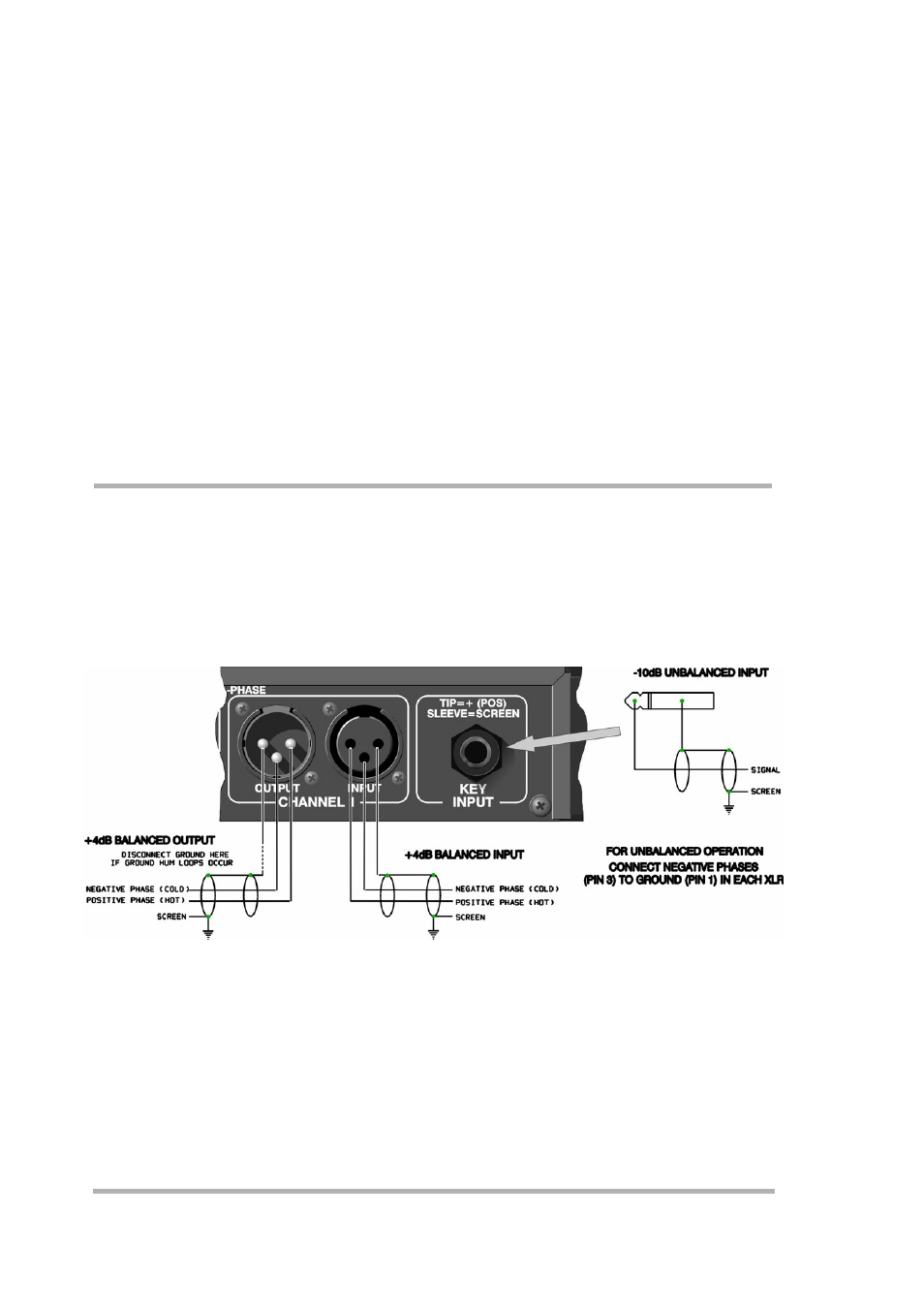
AUDIO CONNECTIONS
Input and Output audio connections are provided via balanced XLRs at a level of
+4dBu. This applies to both inputs and outputs. The wiring convention being:
Pin 1 Ground;
Pin 2 Hot(+);
and Pin 3 Cold(-).
For use with unbalanced systems, the Cold pin 3 must be grounded at both input and
output inside the XLR connectors. For connection to a patch bay, input sockets
should be wired ‘fully normalised’.
The key input is an unbalanced ¼" (TRS) jack socket. For connection to a patch bay
this socket should be wired ‘fully normalised’ to prevent erratic triggering.
Interference: If the unit is to be used where it maybe exposed to high levels of
disturbance such as found close to a TV or radio transmitter, we advise that the unit
is operated in a balanced configuration. The screens of the signal cables should be
connected to the chassis connection on the XLR connector as opposed to connecting
to pin1. The MX40 conforms to the EMC standards.
Ground Loops: If ground loop problems are encountered, never disconnect the
mains earth, instead, try disconnecting the signal screen on one end of each of the
cables connecting the outputs of the MX40 to the patchbay. If such measures are
necessary, balanced operation is recommended.
4