D.A.S. Audio AXA-3RF15 User Manual
Manual del usuario / user’s manual
UM_3RF_01
AXA-3RF12 / AXA-3RF15
MANUAL DEL USUARIO / USER’S MANUAL
D.A.S. AUDIO S.A.
www.dasaudio.com
Garantía
Todos nuestros productos están
garantizados por un periodo de 24
meses desde la fecha de compra.
Las garantías sólo serán válidas si
son por un defecto de fabricación y
en ningún caso por un uso
incorrecto
del
producto.
La
reparación en garantía cubre la
reposición
de
las
partes
defectuosas. Otros cargos como
portes y seguros, son a cargo del
comprador en todos los casos. Para
solicitar reparación en garantía es
imprescindible que el producto no
haya sido previamente manipulado e
incluir una fotocopia de la factura de
compra.
Warranty
All
D.A .S.
products
are
w a r r a n t i e d
a g a i n s t
a n y
manufacturing defect for a period
of 2 years from date of purchase.
The warranty excludes damage
from incorrect use of the product. All
warranty repairs must be exclusively
undertaken by the factory or any of
its authorized service centers. To
claim a warranty repair, do not open
or intend to repair the product.
Return the damaged unit, at
shippers risk and freight prepaid, to
the nearest service center with a
copy of the purchase invoice.
Introducción
Los soportes
AXA-3RF12 y AXA-
3RF15 están diseñados para formar
clusters horizontales de 3 unidades de
Rf-12.85 y/o Rf-12.85 ( AXA-3RF12 ) y
de
Rf-15.85 y/o Rf-15.85 ( AXA-3RF15 ).
Introduction
The
AXA-3RF12 and AXA-3RF15
array frames are designed for
horizontal clusters of 3 units of
Rf-
12.85 and/or Rf-12.85 ( AXA-3RF12 )
and
Rf-15.85 and/or Rf-15.85 ( AXA-
3RF15 ).
C/ Islas Baleares, 24 - 46988 - Fuente del Jarro. Valencia - SPAIN - Tel. 96 134 05 25 - Tel. Intl. +34 96 134 08 60 - Fax +34 96 134 06 07
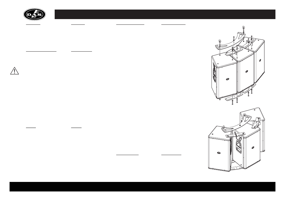
Instrucciones de montaje
1.- Voltear las cajas y desatornillar
los tornillos necesarios para el montaje
y los tacos de goma. Volver a atornillar
los tornillos de los tacos para impedir
la salida de aire.
2.- Posicionar las cajas en el
ángulo deseado.
3.- Atornillar las chapas de unión
a la caja utilizando en los frontales las
cortas y en las traseras las mas largas
(ver dibujo). Los agujeros mas
próximos entre ellos fijan la cajas
lateral con lateral, formando entre ellas
un ángulo de 20º, avanzando hacia el
exterior agujeros alternos de cada lado
incrementamos de 5º en 5º. Es
aconsejable colocar la pieza lo más
simétricamente posible. En la chapa
trasera existen 2 filas de orificios a
cada lado, los externos son para las
Rf
con bajo de 15” y los internos para
12”. La arandela plana debe insertarse
la más próxima a la chapa seguida por
la grower (de presión) y finalmente el
tornillo.
4.- Girar con cuidado las cajas
dejándolas con la parte superior arriba.
5.- Atornillar las piezas de unión
con puntos de volado en la parte
frontal de la caja.
6.- Atornillar la pieza trasera con
tornillo central y anillas de elevación en
los laterales, o en el caso de necesitar
grandes ángulos de inclinación vertical
podemos atornillarla con 3 tornillos y
pasar las anillas a la parte posterior de
las cajas (en este caso las anillas irán
sin arandelas).
7.- Suspender la caja de las
anillas de elevación y de la chapas con
puntos de volado.
Mounting instructions
1.- Flip the speakers upside
down. Remove the existing speaker
screws and rubber feet. Replace the
screws used to attach the rubber feet
to keep air from escaping.
2.- Position the speakers in the
desired splay angle.
3.-Attach the joining plates to the
enclosures using the short plates in
front and the longer plates in the rear
(see drawing). The holes closest to
each other position the enclosures side
to side, forming a 20º angle between
them. Advancing toward the exterior
alternate holes on each side increment
the angles in 5º steps. It is
recommended that the joining plate be
placed as symetrically as possible. On
the rear joining plates are two rows of
holes on each side. The outer holes
are for
Rf enclosres with a 15” bass
and the internal holes are for units with
a 12” bass. Flat washers should be
placed adjacent to the joining plates,
followed by the lock washer and finally
the bolt.
4.- Slowly flip the speaker
assembly so that the tops of the
speakers are facing up.
5.- Screw the joining plates with
rigging points to on the top-front of the
enclosure.
6.- Screw the rear joining plates
to the enclosures using a screw in the
center and eyebolts on the ends. If
steep vertical angling is needed, the
rear plate can be attached with 3
screws and the eyebolts can be used
in the rear (with-out washers in this
case)
7.- Suspend the enclosures using
the eyebolts and the joining plate with
rigging points.
Precauciones de Seguridad
D . A . S .
A u d i o n o s e
responsabilizará
de
usos
no
recomendados de este soporte, ya
sean
debidos
a
la
incorrecta
instalación o a la falta de resistencia de
las estructuras de las que se
suspendan los equipos.
Compruebe periódicamente la
perfecta conservación de los anclajes y
recintos acústicos, sustituyendo los
elementos en los cuales se observen
deterioros.
Afloje los tornillos antes de
reorientar las cajas, nunca fuerce los
elementos de volado.
Si tiene cualquier duda, contacte
con un instalador especializado antes
de proceder al montaje.
Contenido de la caja
4 planchas frontales de union (2 con
puntos de volado), 2 planchas traseras
de union, 14 tornillos M10x30, 14
arandelas Grower M10, 14 arandelas
planas M10, 2 anillas de elevación
M10, 1 llave Allen nº8, 1 llave Allen nº5.
Package contents
4 joining plates (2 with rigging points),
2 rear joining plates, 14 M10x30
screws, 14 Grower (split) M10 lock
washers, 14 M10 flat washers, 2 M10
eyebolts, 1 number 8 Allen (hex)
wrench, 1 number 5 Allen wrench.
Safety Precautions
D.A.S. Audio is not responsible
for use other than the recommended
whether it be the result of insufficient
strength of the support structure or
improper installation of the equipment.
To ensure optimum safety, the
installation
should
be
checked
thoroughly at regular intervals replacing
all deteriorated elements.
Loosen
the
screws
before
reorienting the speaker. Never force the
rigging elements.
Contact a licensed rigger if there
is any doubt.