Installation instructions – Cadet C User Manual
Page 2
Installation Instructions
How do I install for
new construction walls?
Figure 1
Face of wall can must
extend
1
/
2
inch or
5
/
8
inch
from face of stud to allow
for thickness of sheetrock.
STEP 1
Mount The Wall Can
How do I install in an existing wall?
STEP 1
Cut Hole In Wall
Route supply wire from circuit breaker to thermostat
to wall can. For models with built-in thermostat, route
supply wire from circuit breaker to wall can. Remove
a knockout and attach the supply wire with a strain
relief connector leaving 10 inches wire lead for later
use. Connect supply ground wire to grounding pigtail
in wall can (See Figure 3). Proceed to PART TWO.
STEP 2
Route Supply Wires
Route supply wire from circuit breaker to thermostat
to wall can. For models with built-in thermostat, route
supply wire from circuit breaker to wall can. Remove
a knockout and attach the supply wire with a strain
relief connector leaving 10 inches wire lead for later
use (See Figure 3). Connect supply ground wire to
grounding pigtail in wall can.
STEP 2
Route Supply Wires
Review the wall can label for correct direction
(as noted by the UP arrows) before mounting the
wall can in the opening. In the VERTICAL mounting
position the elements of the heater assembly will be
at the top, in the HORIZONTAL mounting position the
elements of the heater assembly will be to the left.
Insert wall can into opening. Keeping wall can flush
with wall, secure Model C to wall stud with 2 screws
and Model CT to both wall studs with 4 screws.
Proceed to PART TWO.
Mount Wall Can
Figure 2
Attach wall can to
stud with screws.
(Model C shown)
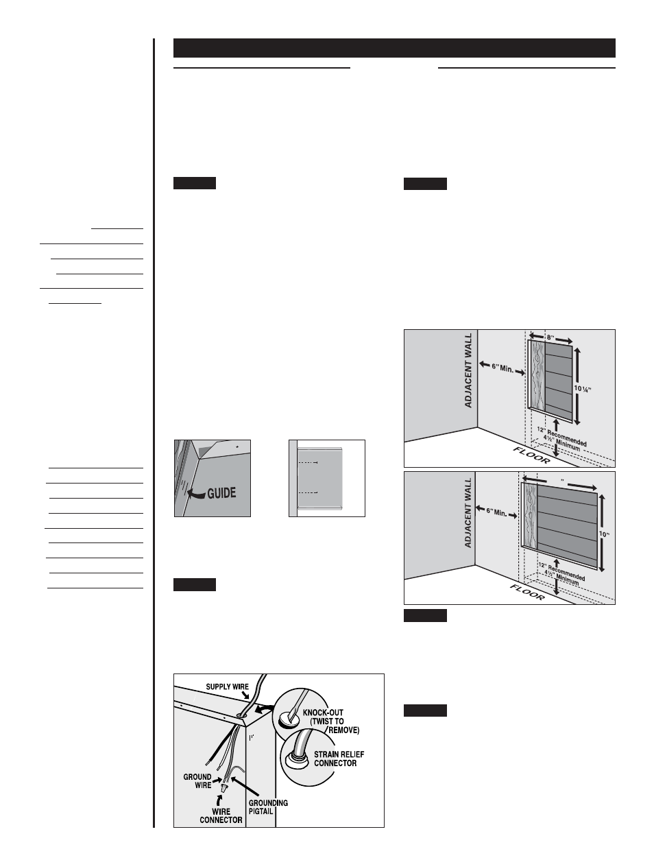
Figure 3
Figure 4
Model C
14
5
/
8
READ ALL
INSTRUCTIONS
AND SAFETY
INFORMATION
IMPORTANT!
It is extremely
important you verify
that the electrical
supply wires are
the same voltage as
the heater (i.e. 120
volt heater to 120
volt power supply
and 240 volt heater
to 240 volt power
supply). If replacing
an existing heater,
check the labels of
the old heater and
replace using the
same voltage.
Hooking a 240 volt
heater to a 120 volt
power supply will
drastically reduce
the heater’s output.
Hooking a 120 volt
heater to a 240 volt
power supply will
destroy the heater.
Connecting your
heater to an
incompatible
power supply will
void the warranty.
Part One
PLACEMENT:
Install The Com-Pak Plus (Model C) vertically (recommended) or horizontally. Model C may be
installed in the ceiling (for models up to 1500W maximum. See ceiling mount instructions.) The Com-Pak Twin Plus
(Model CT) must be installed with the arrows in the wall can pointing upwards.
THERMOSTAT:
A thermostat is required for models without a built-in thermostat. A Cadet Electronic Thermostat or
Cadet Dual Diaphragm Thermostat is recommended for ultimate control and comfort.
Figure 5
Model CT
STEP 3
The C Series REQUIRES A MINIMUM distance of
6 inches from adjacent surfaces and 4
1
/
2
inches from
the floor (See Figure 4) and the CT Series REQUIRES
A MINIMUM distance of 6 inches from adjacent
surfaces and 4
1
/
2
inches from the floor (See Figure 5).
However, Cadet RECOMMENDS 12 inches from all
adjacent surfaces and 12 inches above the floor for
longer and cleaner performance. Heaters must be
spaced at least 3 feet apart.
Review the wall can label for correct direction
(as noted by the UP arrows) before mounting the
wall can in the opening. In the VERTICAL mounting
position the elements of the heater assembly will be
at the top, in the HORIZONTAL mounting position the
elements of the heater assembly will be to the left.
Model C: Secure the wall can to the stud with
2 screws (See Figures 1 & 2). As an option, the rubber
shim provided may be attached to side of wall can to
square the wall can to the stud.
Model CT: Secure the wall can to studs on both sides
with 4 screws.
Model C: Cut a hole 8 inches wide by 10
1
/
4
inches
high next to wall stud. The C Series REQUIRES
A MINIMUM distance of 6 inches from adjacent
surfaces and 4
1
/
2
inches from the floor. However,
Cadet RECOMMENDS 12 inches from all adjacent
surfaces and 12 inches from the floor (See Figure 4).
Model CT: Cut a hole 14
5
/
8
inches wide by 10 inches
high next to wall stud. The CT Series REQUIRES
A MINIMUM distance of 6 inches from adjacent
surfaces and 4
1
/
2
inches from the floor. However,
Cadet RECOMMENDS 12 inches from all adjacent
surfaces and 12 inches from the floor (See Figure 5).
2