Adanger, Water piping system piping installation – Kenmore 153.32116 User Manual
Page 10
Attention! The text in this document has been recognized automatically. To view the original document, you can use the "Original mode".
Water Piping System
Piping Installation
ADANGER
Water temperature over 125°F
(52°C) can cause severe burns
instantly resulting in severe injury
or death.
Children, the elderly, and the
physically or mentally disabled
are at highest risk for scald injury.
Feel water before bathing or
showering.
Temperature limiting valves are
available.
Read instruction manual for safe
temperatures etti ng.
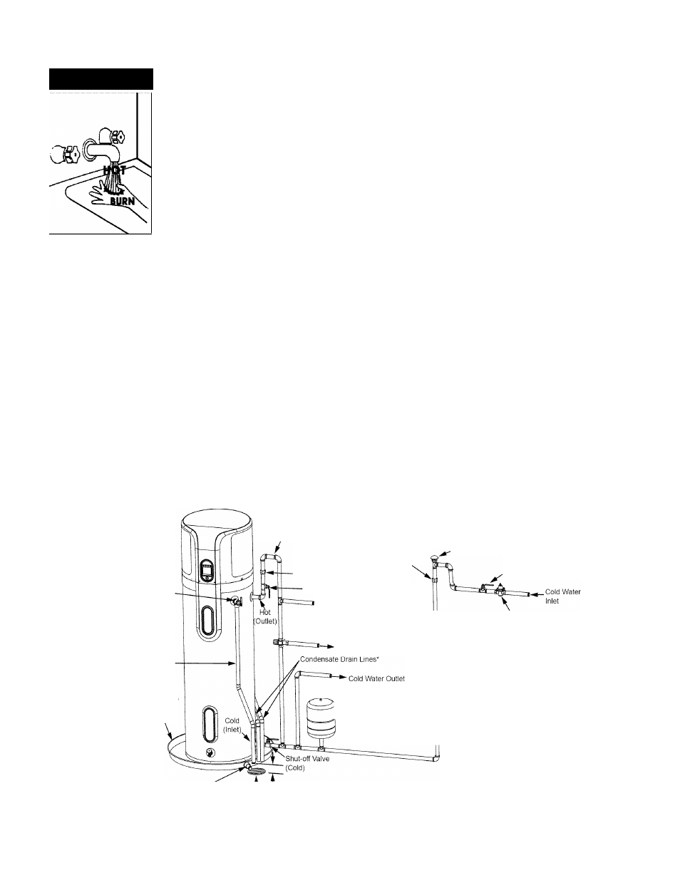
Piping, fittings, and valves should be installed according to the
installation drawing (Figure 9). If the indoor installation area
is subject to freezing temperatures, the water piping must be
properly insulated.
The water supply pressure should not exceed 80 psi. If this
occurs, a pressure reducing valve with a bypass should be
installed in the cold water inlet line. This should be placed on
the supply to the entire house in order to maintain equal hot and
cold water pressures.
IMPORTANT:
*
Heat must not be applied to the water fittings on the
heater as they may contain nonmetallic parts. If solder
connections are used, solder the pipe to the adapter
before attaching the adapter to the hot and cold water
fittings.
•
Always
use
a
good
grade
of
joint
compound
and
be
certain
that
all
fittings
are
tight.
IMPORTANT: DO NOT over apply joint compound.
NOTE: To protect against untimely corrosion of hot and cold
water fittings, it is strongly recommended that di-electric
unions or couplings be installed on this water heater when
connected to copper pipe.
1.
Install the water piping and fittings as shown in Figure 9.
Connect the cold water supply (3/4” NPT) to the fitting
marked “Cold”. Connect the hot water supply (3/4” NPT)
to the fitting marked “Hot”.
2.
The installation of unions in both the hot and cold water
supply lines are recommended for ease of removing the
water heater for service or replacement.
3.
Some local codes may require, and the manufacturer of
this water heater recommends, installing a mixing valve
or an anti-scald device in the domestic hot water line as
shown in Figure 9. These valves reduce the point-of-use
temperature of the hot water by mixing cold and hot water
and are readily available. Contact a licensed plumber or
the local plumbing authority for more information.
4.
Some local codes may require, and the manufacturer
of this water heater recommends, installing a pressure
reducing valve (PRV) in the cold water inlet line where it
enters the residence as shown in Figure 9.
5.
If installing the water heater in a closed water system,
install an expansion tank in the cold water line as specified
under “Closed System/Thermal Expansion.”
6.
Install a shut off valve in the cold water inlet line. It
should be located close to the water heater and be easily
accessible. Know the location of this valve and how to shut
off the water to the heater.
7.
Install a discharge line from the temperature and pressure
relief valve in the opening marked “T & P RELIEF VALVE”.
See Figure 10 and the “Temperature and Pressure Relief
Valve” section.)
Heat Trap - The top of the heat trap
must be higher than the storage tank
of the water heater.
Union.
Union
Temperature and
Pressure Relief Valve
Discharge Pipe
(Do Not Cap or Plug)
Metal Drain Pan 2 1/2’
Depth Maximum and
2 Inches wider than
the water heater.
Massachusetts: Install a vacuum relief in cold
water line per section 19 MGL 142.
Shut-off Valve (Hot)
Untempered Water Outlet
Mixing Valve (Optional) - Follow the
•Mixing Valve’s Manufacturer’s Installation
Instructions. (Setto 120° F)
•Tempered Water to Fixtures
In a closed system, use a
A See “Closed System/
Thermal Expansion”
section.
...Vacuum Relief Valve
Cold Water
Inlet Valve
Whole House Pressure Reducing
Valve (PRV) should be installed
where the water supply enters
the residence.
Drain Line 3/4"^
T
'—6” Maximum
ID Minimum
Air Gap
" If an adequate drain is not available for the condensate drain lines then a condensate pump should be used. DO NOT discharge the condensate drain
lines into the metal drain pan.
FIGURE 9.
10