Troubleshooting, Automatic electronic diagnostics, Manual initiated electronics diagnostics – Kenmore GENIUS II 625.34867 User Manual
Page 22: Озго, Service tech. information, 5a. troubleshooting
Attention! The text in this document has been recognized automatically. To view the original document, you can use the "Original mode".
SECTION 5
SERVICE TECH. INFORMATION
5A.
TROUBLESHOOTING
AUTOMATIC ELECTRONIC DIAGNOSTICS
The faceplate timer (PWA) computer has a self-diag
nostic function for the electrical system, except for
input power and water meter ■ fsitr 9
g
W|
" _
The computer monitors the elec- -
- trrii
tronic components and circuits
for correct operation. If a mal
function occurs, an error code
appears in the faceplate display.
The chart below shows the error codes that could
appear, and the possible defects for each code.
While an enror code appears in the display, all face
plate buttons are inoperable except the SELECT
button. SELECT remains operational so the service
person can make the MANUAL INITIATED ELEC
TRONIC DIAGNOSTICS (below) to further isolate the
defect, and check the water meter.
CODE
POSSIBLE DEFECT
MOST LIKELY _ ^ LESS LIKELY
■ ^
Erri
motor inoperative / wiring harness or connection to switch / position switch / faceplate timer (PWA)
ЕггЗ
motor / faceplate timer (PWA)
See faceplate timer (PWA) replacement
on page 23.
Err4
timer (PWA) / position switch
Err5
faceplate timer (PWA)
PROCEDURE FOR REMOVING ERROR CODE FROM FACEPLATE:
1. Unplug transformer 2. Correct defect
3. Plug in transformer 4. Wait for 6 minutes. The error code will return if the defect was not corrected.
MANUAL INITIATED ELECTRONICS DIAG
NOSTICS
1.
To enter diagnostics...
—from a error code display, press the #1 SELECT
button.
—from a time display, press and hold the #1
SELECT button for 3 seconds.
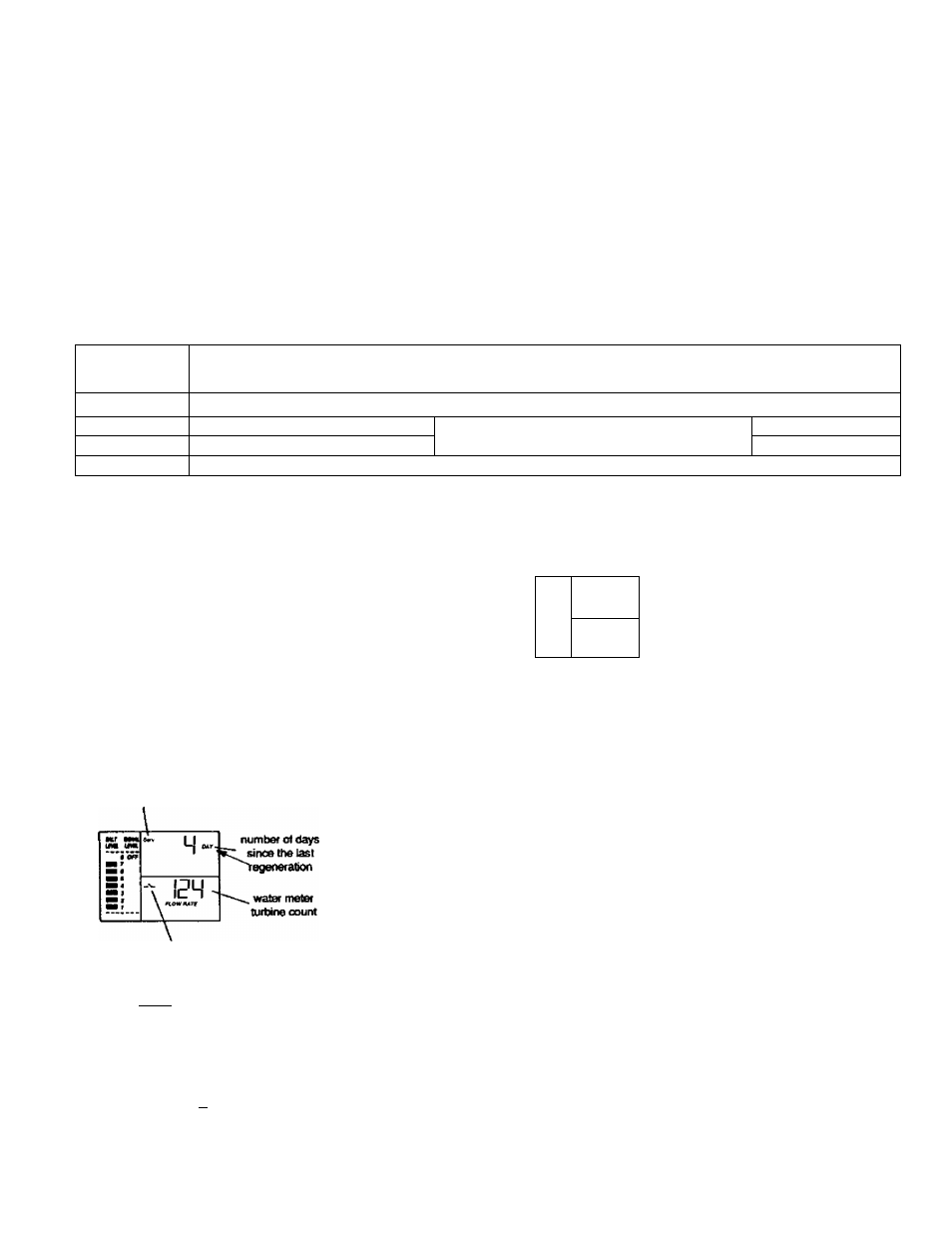
You will see 1 of the following displays. All of the
displays show what position the valve is in, if the
turbine is operating, and the position switch open or
closed status.
valve position indicatar
VALVE IN SERVICE
POSITION
position switch indicator
(open)
valve риМоп Indicalor
■озго
033-
. mimitesatlU
cyde remaining
VM.VE IN A RECHARGE
POSmON (FILL, IN THIS
-watermelBr EXAMPLE)
turbine count
valve position indicator
arvd Brine flashing)
iir
ШЛ
(M Шк.
Ш»
iOO'
TIHCMBtUiMIM
s# *
-Г
Q00-.
\ АЮИГМТЕ
position switch indicator
(dosed)
minutes ol brining time
(begins to count down
when valve reaches
brining poeilkxi) VALVE ROTATING
FROM 1 RECHARGE
POSITION TO
«JOTHER (FROM
FUXTOBRIHIHQ IN
THIS EXAMPLE)
turbine count
position swHeh Indicaior
(open)
2.
Press the ON/OFF-HOLD button to advance the
valve to the next position. To verify component
operation, or to possibly isolate a defea, observe
the following.
POSITION SWITCH STATUS: With the valve in service,
or any of the recharge cycles, the switch indicator will
show open -N-, While the valve is rotating from 1
position to another, the indicator will show the switch
closed A defect is probable if indications vary
from this pattern.
WATER METER TURBINE: With soft water in use, the
turbine flow rate display continually repeats a 000 to
140 count for each gallon of water passing through the
turbine. The display will remain a steady...000 if soft
water is not in use (open a nearby soft water faucet to
check).
If you don’t get a reading in the display, with faucet
open, pull the sensor from the valve outlet port. Pass a
small magnet back and forth in front of the sensor. You
22