A. troubleshooting, Automatic electronic diagnostics, Code – Kenmore ULTRASOFT 400 625.38845 User Manual
Page 23: Possible defect, Manual initiated electronics diagnostics, Service tech. information
Attention! The text in this document has been recognized automatically. To view the original document, you can use the "Original mode".
SECTION 5
j jjj j jj
1
SERVICE TECH. INFORMATION
A. TROUBLESHOOTING
AUTOMATIC ELECTRONIC DIAGNOSTICS
The faceplate timer (PWA) computer has a self
diagnostic function for the electrical system, except
for input power and water meter. The computer
monitors electronic components
”
”
and circuits for correct opera
tion. If a malfunction occurs, an
error code appears in the face
plate display.
£VEIL£VEL
в
7
6
Ё г г З
4
5
2
The chart below shows the error codes that could
appear, and the possible defects for each code.
While an error code appears in the display, all face
plate buttons are inoperable except the SELECT but
ton. SELECT remains operational so the service per
son can make the MANUAL INITIATED ELEC
TRONIC DIAGNOSTICS (below) to further isolate
the defect, and check the water meter.
CODE
POSSIBLE DEFECT
MOST LIKELY
^ LESS LIKELY
Erri, ЕггЗ,
Err4
motor inoperative / wiring harness or connection to switch / position switch / vaive defect causing
high torque
Err5
faceplate timer (PWA)
PROCEDURE FOR REMOVING ERROR CODE FROM FACEPLATE:
1. Unplug transformer 2. Correct defect 3. Plug
in transformer 4. Wait for 6 minutes. The error code will return if the defect was not corrected.
MANUAL INITIATED ELECTRONICS
DIAGNOSTICS
To enter diagnostics...
- - from a error code display, press the SELECT 1
button.
--from a time display, press and hold the SE
LECT 1 button for 3 seconds.
You will see one of the following displays. AE of the
displays show what position the valve is in, if the
turbine is operating, and the position switch open or
closed status.
valve position indicabx
I
L!
i ^ 4
number of days
since the last
^regeneration
. water meter
turbine count
VALVE IN SERVICE
POSITION
position switch indicator
(open)
valve poelUon mdicator
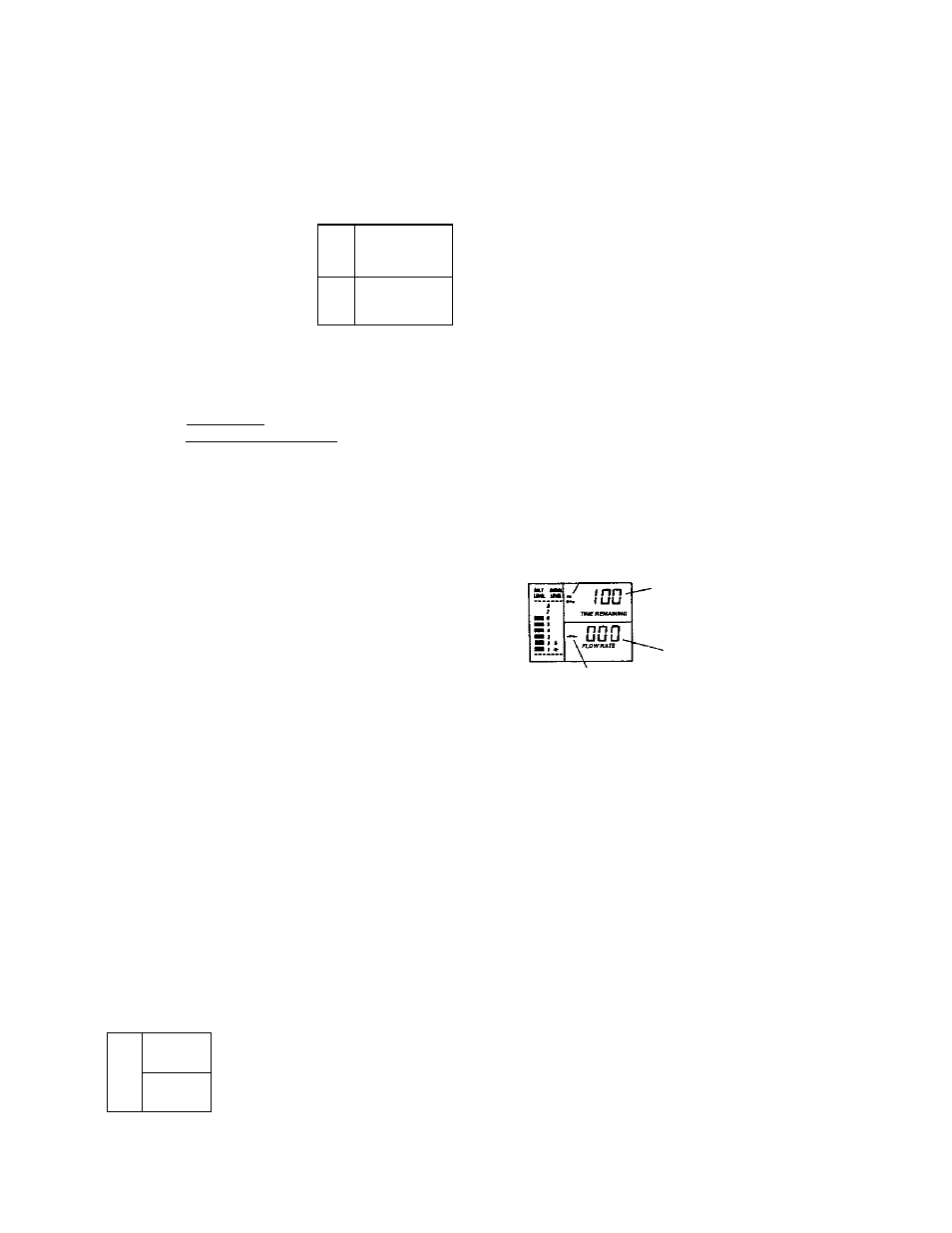
№
UHI uw
тшгяемлмша
MJ
Y 033-
«Wl »
\ FLOW HATE
_ minutes of Ml
cycle remaining
- water meter
turbine count
VALVE IN A RECHARGE
POSmON (FILL. IN THIS
EXAMPLE)
position switch Indicator
(open)
valve position indicc№r
(Fill and Brine Dashing)
position switch Indicaur
(dosed)
minutes of biinlng time
(begins to count down
when valve reaches
brining position) VALVE ROTATING
FROM 1 RECHARGE
POSITION TO
ANOTHEB (FROM
FILL TO BRINING IN
THIS EXAMPLE)
POSITION SWITCH STATUS: With the valve in ser
vice, or any of the recharge cycles, the switch indica
tor win show open . While the valve is rotating
from 1 position to another, the indicator will show
the switch closed
. A defect is probable if indica
tions vary from this pattern.
WATER METER TURBINE: With soft water in use,
the turbine flow rate display continually repeats a
000 to 140 count for each gallon of water passing
through the turbine. The display wrli remain a
steady.. .000 if soft water is not in use (open a nearby
soft water faucet to check).
If you don't get a reading in the display, with facuet
open, puU the sensor from the valve outlet port.
Pass a small magnet back and forth in front of the
sensor. You should get a reading in the display. If
you get a reading, unhook the in and out plumbing
and check the turbine for binding.
5 - 2
Problems, Questions? Call 1-800-426-9345 Kenmore Water Line