Installing an interface module -3, Figure 3-1, Reset – Cabletron Systems 6H258-17 User Manual
Page 33: Plastic locking tab slot number
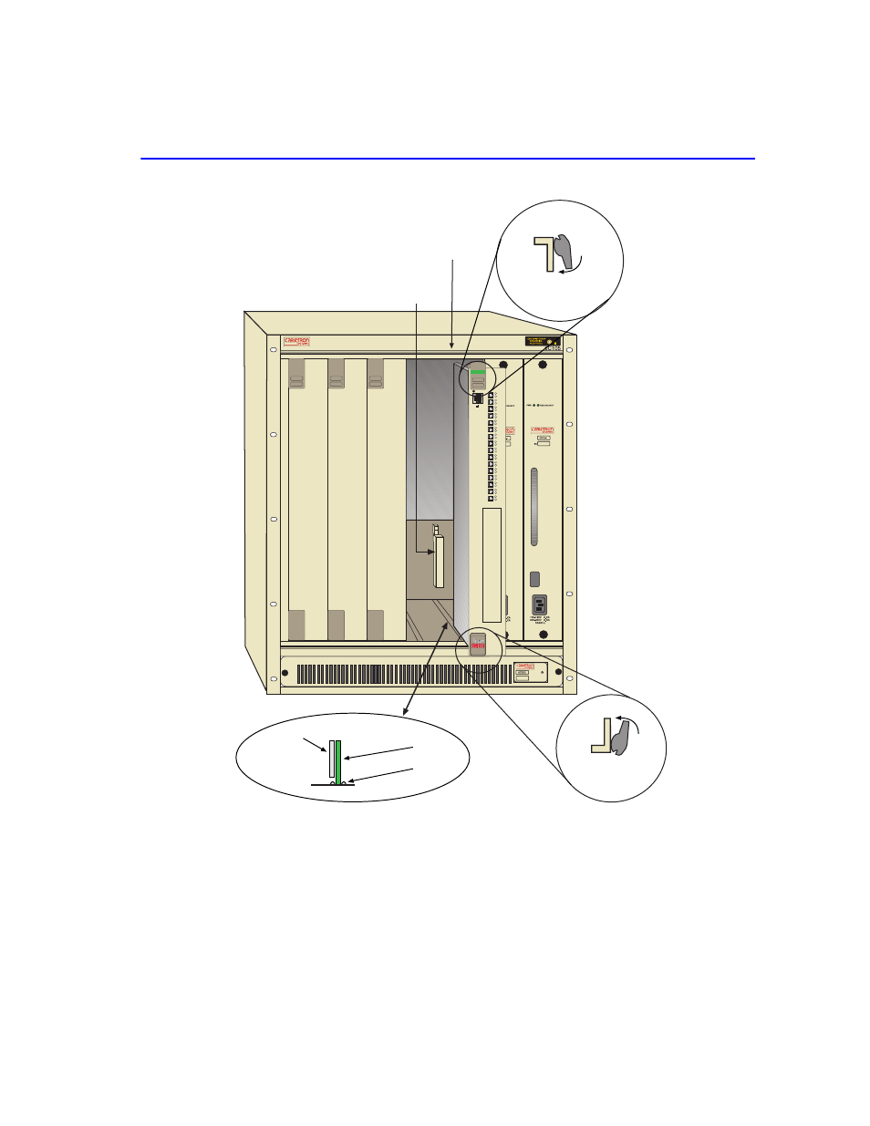
Installing the SmartSwitch into the 6C105 Chassis
Installation
3-3
Figure 3-1
Installing an Interface Module
5.
Examine the module for damage. If any damage exists, DO NOT install the module.
Immediately contact Cabletron Systems. Refer to
1
2
3
4
5
PS1
PS2
Plastic
Locking Tab
Slot Number
2159-01
Circuit Card
Card Guides
Metal Back-Panel
Plastic Locking Tab
Backplane
Connector
C
O
M
CPU
6H253-17
Fast Enet
RESET
2
RX
TX
4
RX
TX
3
RX
TX
6
RX
TX
5
RX
TX
8
RX
TX
7
RX
TX
10
RX
TX
9
RX
TX
12
RX
TX
11
RX
TX
14
RX
TX
13
RX
TX
16
RX
TX
15
RX
TX
1
RX
TX
This manual is related to the following products:
See also other documents in the category Cabletron Systems Hardware:
- FOT-F3 (41 pages)
- FOT-F3 (44 pages)
- BRIM-F6 (41 pages)
- WPIM-RT1 (50 pages)
- BRIM-WT1 (32 pages)
- 36 (33 pages)
- 9T101-04 (28 pages)
- FDDI Repeater (29 pages)
- SWPIM-BRI (34 pages)
- 9C114 (26 pages)
- SMARTSWITCH ROUTER 9032578-05 (398 pages)
- HSIM-W6 (258 pages)
- NB25 E (30 pages)
- HSIM-G01 (36 pages)
- HSIM-FE6 (42 pages)
- Expansion module 9E429-36 (18 pages)
- EMM-E6 Ethernet (205 pages)
- Environmental Module TM 9C300-1 (50 pages)
- CSMIM-T1 (198 pages)
- NBR-620 (73 pages)
- E2100 (42 pages)
- KBU64 Rackmount (26 pages)
- AirConnect 3Com (93 pages)
- 802.1Q (92 pages)
- W85 (60 pages)
- ELS10-26 (170 pages)
- Expansion module 9E106-06 (40 pages)
- Expansion module 9F120-08 (12 pages)
- EMC39-12 (33 pages)
- 6A000/ZX-250 (268 pages)
- Expansion module DELHE-UA (50 pages)
- Expansion module 9T122-08 (36 pages)
- DMS-100 (196 pages)
- BRIM E100 BRIM-E100 (42 pages)
- Cabletron CyberSWITCH CSX400 (275 pages)
- Cabletron SmartSwitch Router 250 (34 pages)
- Network Router (100 pages)
- 9W111-08 (28 pages)
- CSX400 (101 pages)
- Cabletron SmartSwitch Router 510 (106 pages)
- SEHI-32/34 (90 pages)
- SmartSwitch (338 pages)
- 9T106-01 (28 pages)
- Switch 9H531-17 (38 pages)