Danger, Installation instructions, Unit wiring diagram – Whirlpool 50 User Manual
Page 7
Attention! The text in this document has been recognized automatically. To view the original document, you can use the "Original mode".
Installation Instructions
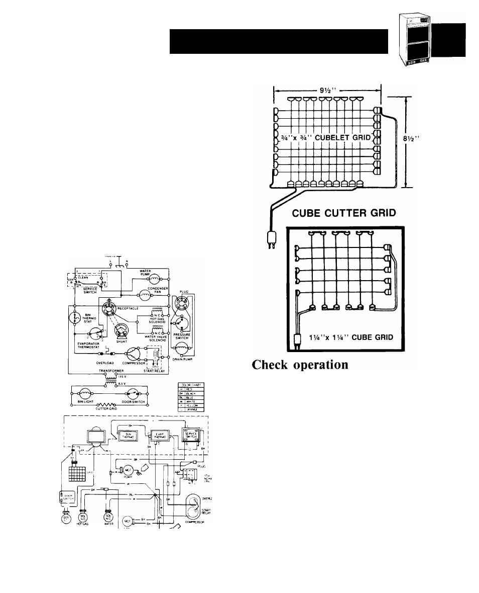
Unit wiring diagram
This model operates at 115 volts except for the cutter
grid circuit which operates at 8.5 volts at 1 amp.
The compressor runs at all times except when the bin
thermostat becomes satisfied and opens up. This de
energizes the system except for the transformer and
cutter grid.
Under
normal
operating
conditions,
when
the
evaporator reaches the preset temperature (-i-10° to
-3° F, depending on thickness of ice) the evaporator
thermostat
opens,
terminating
operation
of
the
fan
motor and pump motor. The hot gas solenoid and the
water valve solenoid are energized at this time and re
main so until the evaporator reaches 38 -i- 2°F.
DANGER:
ELECTRIC SHOCK HAZARD disconnect power
before servicing unit. Maximum fuse size: 15
amps.
CUBELET CUTTER GRiDS
Start the unit by turning the service switch to
“ON” and opening the line water valve.
NOTE: Left is “OFF” — Middle is “ON” — Right
is
“CLEAN.”
In
“CLEAN”
position,
only
the
pump operates.
Check
condenser
fan
to
make
sure
it
is
revolving.
Water will not enter pump pan until freezing
plate gets cold and machine goes into a harvest
cycle.
Check for even water flow over freezing plate.
Unit must be level for proper operation.
-------g-C
Check for desired cube thickness and after 24
hours adjust if necessary. Maximum ice yield will
be obtained with ice thickness at V
2
” to
Replace grill.