Carl Goldberg GPMA1959 Sophisticated Lady Glider ARF User Manual
Page 12
12
3. Move the elevator up with your transmitter and move the
ruler forward so it will remain contacting the trailing edge. The
distance the elevator moves up from center is the “up” elevator
throw. Measure the down elevator throw the same way.
The pushrod farther out
means
More Throw
The pushrod closer in
means
Less Throw
At the Servos
The pushrod farther out
means
Less Throw
The pushrod closer in
means
More Throw
At the Control Surfaces
4. If necessary, adjust the location of the pushrod on the
servo arm or on the elevator horn, or program the ATVs in
your transmitter to increase or decrease the throw according
to the measurements in the control throws chart.
5. Measure and set the
low rate
elevator throws and the
high and low rate throws for the rudder control surface the
same way.
If your radio does not have dual rates, we recommend
setting the throws at the high rate settings.
NOTE
: The throws are measured at the
widest part
of
the elevator and rudder.
These are the recommended control surface throws:
HIGH RATE
LOW RATE
ELEVATOR
3/8"
[9.5mm]
22 deg
Up
3/8"
[9.5mm]
22 deg
Down
3/16"
[4.8mm]
11 deg
Up
3/16"
[4.8mm]
11 deg
Down
RUDDER
1-1/2"
[38mm]
24 deg
Right
1-1/2"
[38mm]
24 deg
Left
1"
[25.4mm]
16 deg
Right
1"
[25.4mm]
16 deg
Left
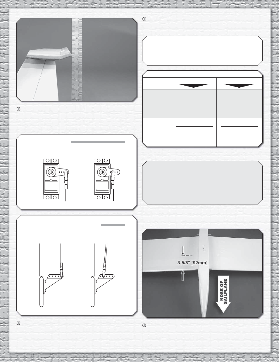
BALANCE THE MODEL (C.G.)
More than any other factor, the C.G. (center of gravity/
balance point) can have the greatest effect on how a
model fl ies and could determine whether or not your fi rst
fl ight will be successful. If you value your model and wish
to enjoy it for many fl ights,
DO NOT OVERLOOK THIS
IMPORTANT PROCEDURE.
A model that is not properly
balanced may be unstable and possibly unfl yable.
At this stage the model should be in ready-to-fl y condition
with
all
of the components in place including the complete
radio system.
1. If using a Great Planes C.G. Machine, set the rulers to
3-5/8" [92mm]. If not using a C.G. Machine, use a fi ne-point
felt tip pen to mark lines on the bottom of the wing on both
sides of the fuselage 3-5/8" [92mm] back from the leading