Flap & aileron pushrods, Stabilizer – Carl Goldberg GBGA1042 User Manual
Page 5
5
2.
Remove the covering on both the ailerons &
the flaps, where the control horn slots are
located.
Using CA glue, attach the control horns to the
ailerons and flaps.
3.
Find the small aileron pushrod wire, and place
a “z” in one end.
1.
Collect the following parts:
(1) Wing
(4) Control Horns
(4) EZ connectors with screws and nylon nuts.
(4) Short Pushrod Wires
Flap & Aileron Pushrods
4.
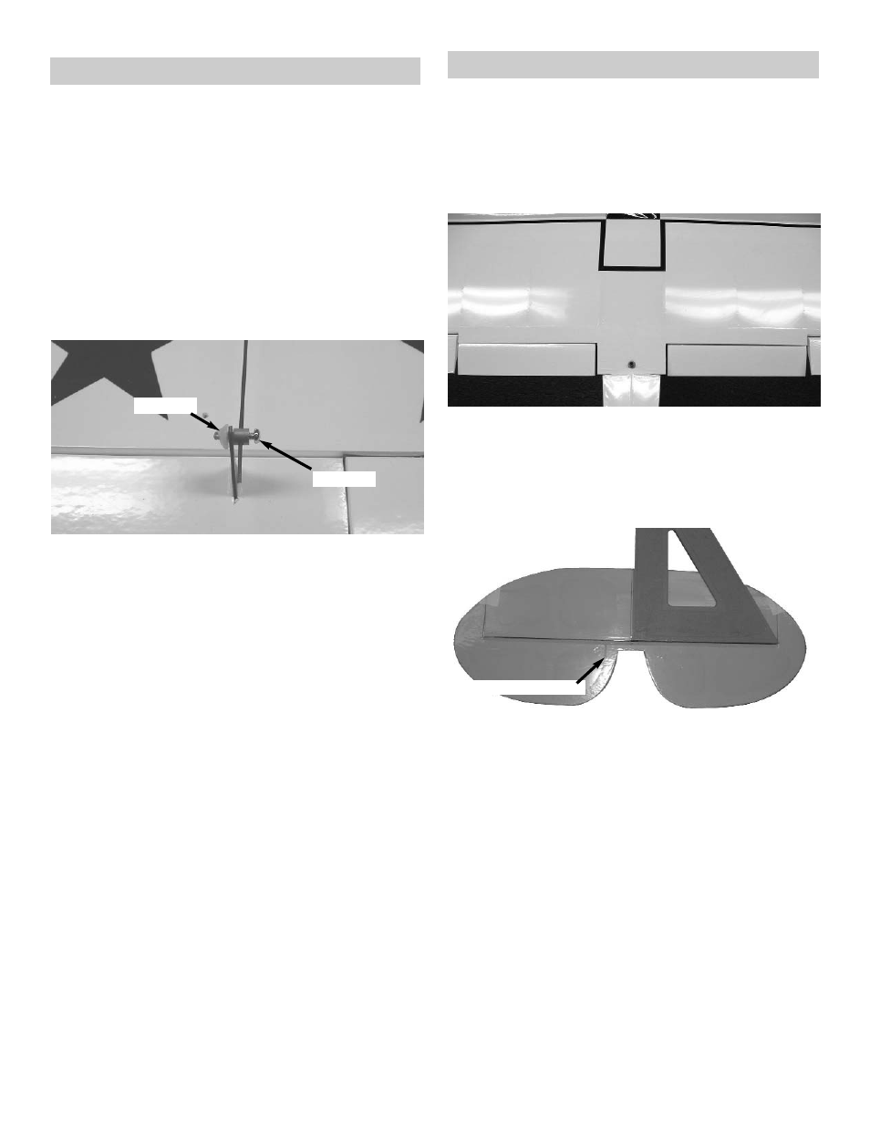
Connect the EZ pushrod connector to the
Control horn.
Put the “Z” bend into the outer hole of the
servo arm.
Slide the pushrod wire through the connector
on the control horn and mount the arm onto
the servo.
Tighten the set screw onto the pushrod.
5.
Repeat these steps for the other aileron and
flap pushrods.
Snap Nut
Set Screw
Stabilizer
1.
Collect the following parts:
(1) Fuselage
(1) Stabilizer & Elevator
(1) wing
(1) 4-40 x 3/8” Socket Head Bolt
(1) #4 Washer
2.
Locate the hole in the center of the wing for
the wing bolt. Remove the covering over the
hole.
Using the 4-40 x 3/8” socket head screw and
the #4 Washer, bolt the wing to the fuselage.
3.
Place the stabilizer top side up on your work
bench
Find the center of the stabilizer, by measuring
the length of the trailing edge where the ele-
vator hinge line is located.
Stand the stabilizer up on its edge and using
a right triangle draw a center line up from the
trailing edge to the leading edge.
Find the center of the fuselage in front of
where the stabilizer sits.
Place the stabilizer on the fuselage using the
marks you just made.
Top of stab shown
Elevator control horn slot