CAMCORP Blower Package with Roots Blower User Manual
Page 31
8
For your nearest ROOTS Office, dial our Customer Service Hot Line 1 877 363 ROOTS (7668).
O
PERATING
C
HARACTERISTICS
ROOTS
™
rotary blowers and exhausters, as covered in
this manual, are available in basic frame sizes ranging
from 2 inch to 7 inch gear diameter. Various models,
within this gear diameter range, are available with dif-
ferent case lengths to produce reasonable steps in flow
capacity. The shorter case lengths have lower
volumetric capacities, but are capable of operating
against higher pressures. All models are available for
air service and there are specifically designed models
for gas service.
The basic ROOTS
™
rotary lobe blower is a positive
displacement type unit. Flow capacity is determined by
frame size, operating speed and pressure conditions.
It employs two impellers mounted on parallel shafts
rotating in opposite directions within a cylinder closed
at the ends by head-plates. As the impellers rotate,
gas is drawn into one side of the cylinder and forced
out the opposite side. The pressure or vacuum
developed depends on the resistance of the piping
and process system.
The unit is a precision engineered product with very
fine clearances between the rotating impellers and
stationary case. Since there is no actual contact
between these surfaces, internal lubrication is not
required. Clearances are maintained by a pair of
accurately machined timing gears, mounted on the
two shafts extended outside the blower casing.
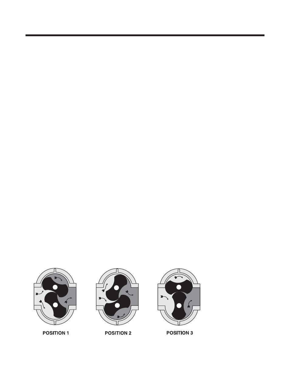
Operation of the familiar basic rotary lobe blower is
illustrated in FIGURE 1, where air flow is left to right
from inlet to discharge with the top impeller rotating
clockwise. In Position 1 it is delivering a known volume
(B) to the discharge, while space (A) between the
lower impeller and cylinder wall is being filled.
Counterclockwise rotation of this impeller then traps
equal volume (A) in Position 2, and further rotation
delivers it to the discharge in Position 3.
One complete revolution of the driving shaft alternately
traps four fixed and equal volumes of air (two by each
impeller) and pushes them through to the discharge.
The volume capacity of a lobe blower operating at a
constant speed therefore remains relatively independ-
ent of reasonable inlet of discharge pressure variations.
To change capacity, it is necessary either to change
speed of rotation or blow off some of the discharge air.
No attempt should ever be made to control capacity
by means of a throttle valve in the intake or discharge
piping. This will not only increase the power load on the
driver, but can also overload and seriously damage the
blower. If a possibility does exist that flow to the blower
inlet may be cut off during normal operation of a
process, then an adequate vacuum relief valve must
be installed near the blower. A pressure type relief
valve in the discharge line near the blower is required
for protection against cut-off or blocking in this line.
Refer to FIGURE 3 for a complete piping schematic.
When a belt drive is installed, blower speed can usually
be adjusted to obtain desired capacity by changing the
diameter of one or both sheaves. In a direct coupled
arrangement a variable speed motor or transmission
is required, or excess air may be blown off through
a manually controlled unloading valve and silencer.
If returned to the blower inlet, the air must be cooled
to 100°F (38°C) through a by-pass arrangement to
maintain acceptable blower temperatures.
Before making any change in blower capacity, or
operating conditions, contact ROOTS for specific
information applying to your particular blower. In all
cases, operating conditions must be maintained within
the approved range of pressures, temperatures and
speeds as stated under LIMITATIONS. The air blower
must not be used to handle liquids or solids as serious
damage to the rotating parts may result.
F
IGURE
1 – F
LOW
T
HROUGH A
B
ASIC
R
OTARY
L
OBE
B
LOWER
A
B
A
B
A
B