Asco valves – CAMCORP Blower Package with Duroflow Blower User Manual
Page 45
50-60 Hanover Road, Florham Park, New Jersey 07932
ASCO Valves
Page 2 of 4
Form No.V7050R1
Piping/Tubing (Pressure Transducer)
Adequate support of piping and proper mounting of switch should be made
to avoid excessive shock or vibration. To minimize the effect of vibration on
a switch, mount perpendicular to vibration. Connect piping or tubing to
switch at base of transducer. It is recommended that flexible tubing be used
whenever possible. Apply pipe compound sparingly to male pipe threads
only. If applied to female threads, it may enter the transducer and cause opĆ
erational difficulty. Avoid pipe strain on switch by properly supporting and
aligning piping. When tightening pipe, do not use switch as a lever. Wrenches
applied to transducer body or piping are to be located as close as possible to
connection point.
IMPORTANT: For steam service, install a condensate loop (pigtail or steam
syphon tube) directly into the pressure transducer.
CAUTION: To avoid damage to the transducer body, DO NOT OVERTIGHĆ
TEN PIPE CONNECTIONS. If TEFLON* tape, paste or similar lubricant
is used, use extra care due to reduced friction.
IMPORTANT: To eliminate undesirable pressure fluctuations in the
system, install a surge suppressor.
Wiring
Wiring must comply with local codes and the National Electrical Code. The
general purpose switch enclosure is provided with a 7/8I diameter hole to
accommodate 1/2I electrical hub or connector. The watertight switch
enclosure has a 1/2I conduit hub. It is recommended that a flexible conduit
connection be used. If rigid conduit is used, do not consider it or use it as a
means of supporting (mounting). Use No. 14 AWG copper wire rated for
60_C minimum. Electrical connections are .187I (3/16) spade type quick
connect terminals. Snap switches accept MOLEX INCORPORATED's
connector (Order No. 05-06-0304) and connector housing (Order No.
06-02-3031).
IMPORTANT: Electrical load must be within range stated on nameplate.
Failure to stay within the electrical range of the switch rating may result in
damage to or premature failure of electrical switch.
CAUTION: Do not exert excessive screw driver force on snap switch when
making terminal connections. When connections are made, be sure there is
no stress on the wire leads. Either condition may cause malfunction of
switch.
ELECTRICAL RATINGS
Switch
Unit
Ratings for Limit Controls and
Pressure Operated Switches
Ratings for Industrial Controls
and Temperature Indicating and
Regulating Equipment
Standard
Switch
Rating
2 Amps Res., 125/250 VAC
1/8 HP 125 VAC
1/4 HP 250 VAC
1/2 Amp Res., 125 VDC
1/4 Amp Res., 250 VDC
10 Amps Res., 125/250 VAC
1/3 HP 125/250 VAC
1/2 Amp 125 125 VDC
1/4 Amp 250 VDC
125 VA PILOT DUTY 120/240 VAC
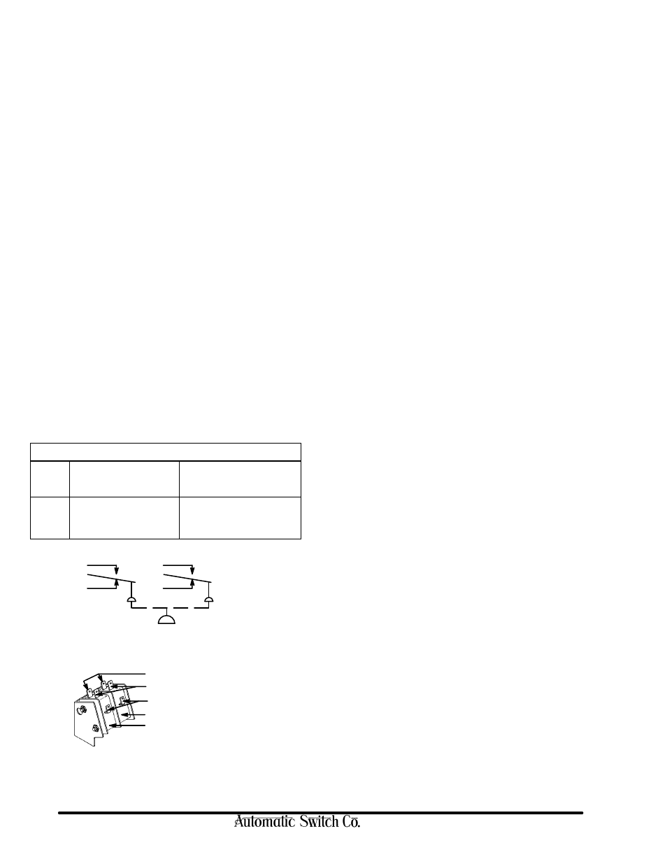
N.O.
N.C.
C
N.O.
N.C.
C
normally open contacts
normally closed contacts
common contacts
high signal setting (right)
low signal setting (left)
SCHEMATIC
DPDT
ELECTRICAL TERMINALS
Electrical terminals are .187
I
spades arranged as:
*DuPont's Registered Trademark
INSTALLATION OF TEMPERATURE TRANSDUCERS
Direct Probe
The direct probe (local) temperature transducer is provided with 1/2I NPT
connection. When installing, do not use switch unit as a lever for tightening.
Use wrenching flats provided at base of transducer for tightening.
Capillary and Bulb
The capillary and bulb (remote) temperature transducers are provided with
a length of capillary and a 3/8I diameter sensing bulb.
CAUTION: Do not bend capillary at sharp angles. For proper operation, be
sure sensing bulb is completely immersed in fluid and not in contact with
heating element or anything that would directly affect the temperature of the
fluid being sensed.
Thermal Well (Optional Feature)
A thermal well may be used for capillary and bulb (remote) or direct probe (local)
temperature transducers. The thermal well affords protection for the sensing
bulb and allows removal of the sensing bulb while maintaining a pressure tight
vessel. When installing sensing bulb in thermal well, be sure that it is fully
inserted. Where a thermal well already exists, jam nuts may be obtained to adapt
the capillary and bulb to the existing thermal well. The existing thermal well must
be for a 3/8I diameter sensing bulb.
Union Connector (Optional Feature)
A union connector will allow direct mounting of the sensing bulb in the fluid
being controlled. Install union into piping connection before tightening
union onto bulb. For maximum performance, the bulb should be inserted in
the union connection so that the end of the sensing bulb is even with the end
of the union connector nut. Do not apply excessive torque when
tightening union connector nut.
Adjustment (Signal Setting) of Two-Stage Fixed
Deadband Switch
When facing switch in the upright position, the adjusting nut on the highest
point controls the high signal setting. The adjusting nut at the lowest point
controls low signal setting (Refer to Figure 3). To make adjustments, a 1/4I
wrench and a pressure or temperature gage (within suitable range) are
required. If electrical connection (to line of final application) of the switch
is not desirable, a battery-powered test lamp or ohmmeter may be used.
Pressure or temperature range scales may be used for initial signal settings.
These will be accurate within 5%. Adjust switch until pointer is in the middle
of the solid red line below the desired range. For exact signal settings,
proceed as follows:
Adjustment (Signal Setting) of Normally Closed or
Normally Open Switch, Increasing Signal
(Refer to Figure 3)
1. If the switch is in the line of final application when adjustment (signal
setting) is made, be sure switch can be test operated without affecting
other equipment.
2. On general purpose and watertight constructions, remove switch cover.
3. Turn high signal adjusting nut until high signal setting indictor is fully
up. Then turn low signal adjusting nut until low signal setting indicator
is fully up. Use a 1/4I wrench for adjusting nuts.
CAUTION: Adjusting nut will turn easily until it hits a stop. Do not
over torque. Over torquing may cause damage.
4. Follow the steps in the chart below to make signal settings. Test one snap
switch at a time. Be sure to start with low signal side.