5 module assembly adjustments, Examples of module assembly issues – C&D Technologies RS-2044 msEndurII Series User Manual
Page 25
RS02044/1114/CD
25
www.cdtechno.com
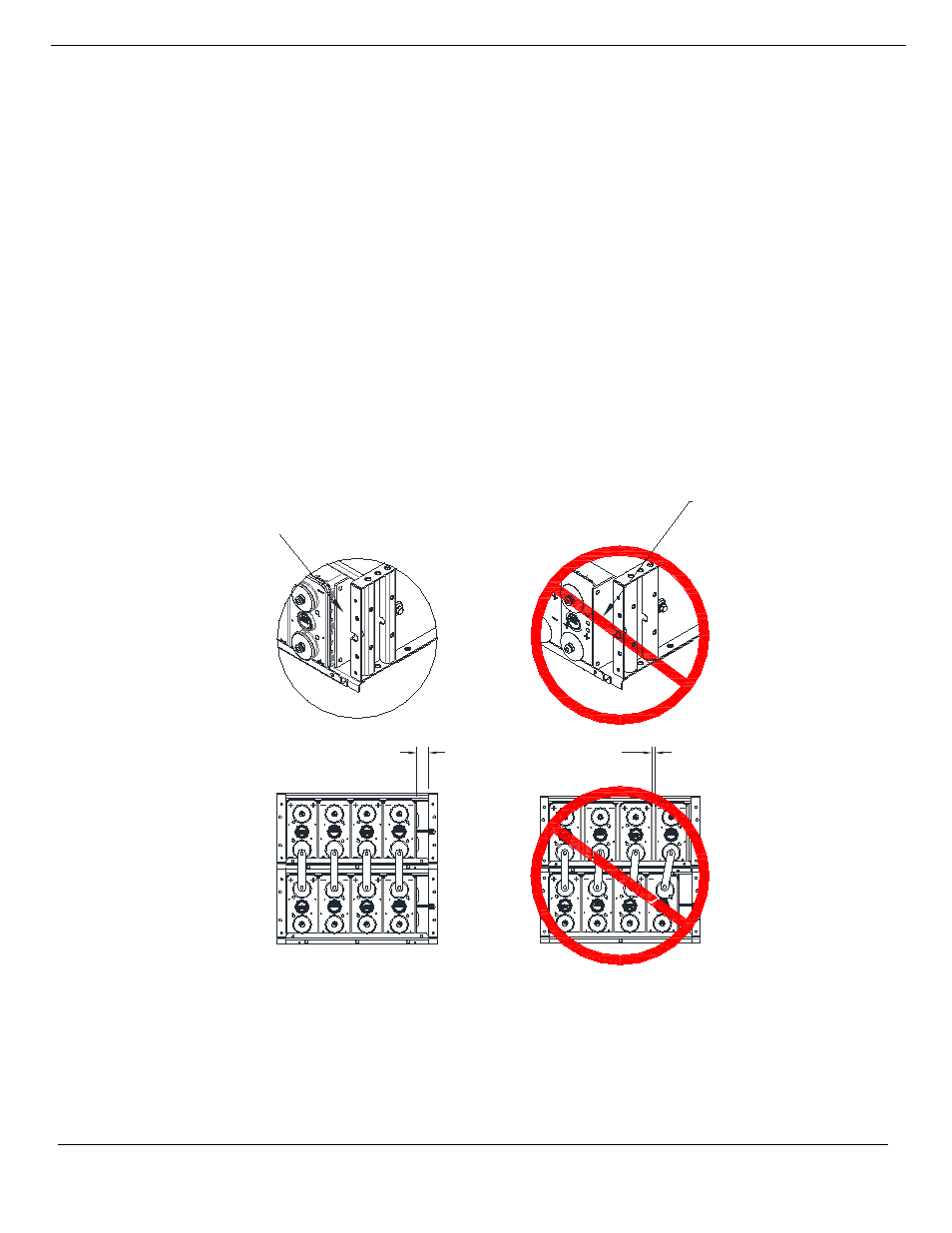
9.5 Module Assembly Adjustments
A module assembly that has been incorrectly assembled in the field should be adjusted to ensure
all cells, cell side restraint plates, cell spacer plates, connectors and hardware are properly aligned
and installed.
Common assembly issues (see Figure 9-1):
1. Connectors not plumb and vertical (due to large cell cover spacing) and the GAP is not
within specifications noted in Table 2 in Appendix C
2. Side restraint bolts not straight
3. Cell side restraint plates and/or cell spacer plates extending beyond the lower lip of the
module
4. Cell side restraint plates contacting the jar/cover seal of the cell (too far forward)
Figure 9-1 Module Assembly Issues
PROPER CELL SPACING
AND CONNECTORS
STRAIGHT
AND VERTICAL
IMPROPER CELL
COVER SPACING
AND CONNECTORS
ANGLED
SIDE RESTRAINT
PLATE
PROPER
LOCATION
SIDE RESTRAINT
PLATE
IMPROPERLY
ON JAR/COVER
JOINT
EXAMPLES OF
MODULE ASSEMBLY
ISSUES
CELL
COVER
SPACING
GAP
"Cell side
restraint plate
improperly
seated; needs
to be pushed
towards back