Schematic parts list, 972 unit, Rod & base assembly for 972 – American Diagnostic Corporation (ADC) Diagnostix 972 Assembly User Manual
Page 2: 1 2 3 3a, 12b 7a
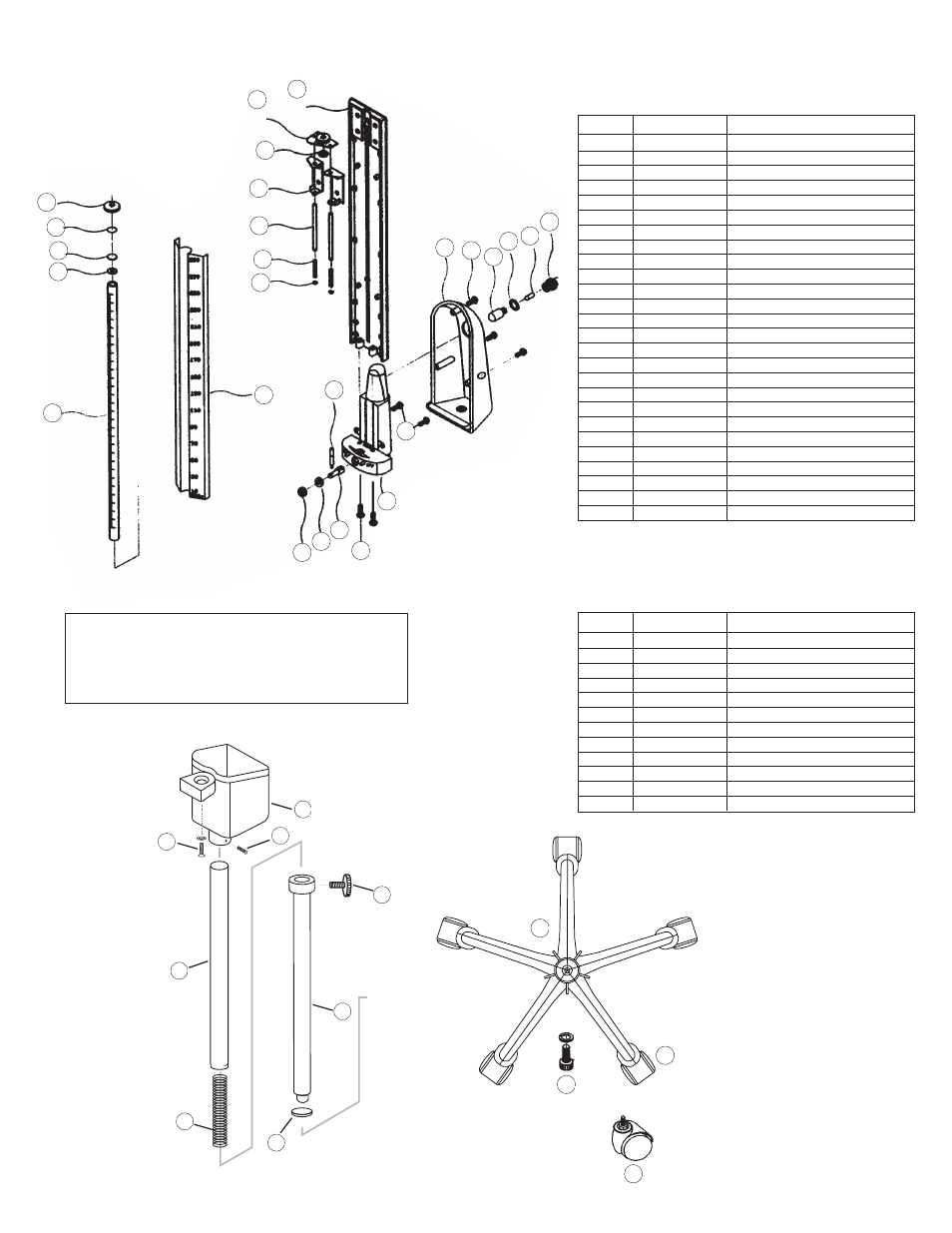
SCHEMATIC PARTS LIST
22
36
23
24
25
26
27
28
29
30
31M
32M
33
34
35
18
19
20
21
7
8
9
10
11
12
Ref #
Item #
Description
13
952-109
Reservoir Connector
14
952-110
Cotton Filter
15
952-111
Reservoir Connector Gasket
15A
952-112
Reservoir Feeder Tube
16
952-113
Reservoir Cover Screws (3)
17M
972-114
Reservoir Cover
18
952-115
Scale Plate Holder
19
952-116
Cartridge Top Plate
20
952-117
Rubber Gasket
21
952-118
Reservoir Holder for Top Plate
22
952-119
Rods (2)
23
952-120
Springs (2)
24
952-121
Locking Washers (2)
25
952-122
Locking Lever Handle
26
952-123
Reservoir Screws (2)
27
952-124
Reservoir Tank
28
952-125
Reservoir Rod
29
952-126
Bushing
30
952-127
Locking Screw (1)
31M
972-128
Scale Plate
32M
972-129
Graduated Plastic Cartridge Tube
33
952-130
Rubber Gasket
34
952-132
Filter Plug
35
952-131
Diaphragm
36
952-133
Screw Cap
37
952-134
Reservoir Base Screws (2)
972 UNIT
Ref #
Item #
Description
1
972-101
Center Pole Screw and Washer (1)
2
972-080
Complete 5 Leg Base
3
972-106
Casters (5)
7
972-107
Outer Pole
7A
972-107A
Rubber Gasket
8
972-108
Knob
9
972-109
Spring
10
972-110
Inner Pole
11
972-111
Tightening Device
12
972-112
Basket
12B
752-114
Manometer Mounting Hardware
3A
972-106-1
Single Caster
ROD & BASE ASSEMBLY FOR 972
13
14
15
16
17M
15A
37
12B
7A
CONNECTING THE INFLATION
SYSTEM TO MANOMETER
Remove red safety cap which seals the reservoir containing mercury. Attach free end of
reservoir tube securely to air inlet. Save red safety cap for later use. When transporting mer-
cury instrument we recommend placing the red safety cap on reservoir.
Please Note: It is normal for negligible amounts of residual mercury droplets to accumulate
around the air inlet beneath the red safety cap during transportation.
1
2
3
3A