American Diagnostic Corporation (ADC) Diagnostix 952B Assembly User Manual
Diagnostix, 952b
DIAGNOSTIX
™
952B
• Wall Mount
Instructions
• Schematics
• Parts List
WALL
MOUNTING
INSTRUCTIONS
MAINTENANCE
CONNECTING THE
INFLATION
SYSTEM TO
MANOMETER
Remove red
safety cap
which seals
the
reservoir
containing mer
cury
(on the
952, the
red safety
cap is
located on
the
air inlet
beneath swivel
base). Attach
free end
of reser
voir tube
securely to
air
inlet. Save
red safety
cap for
later use.
When transporting
mercur
y instrument
we recommend
placing the
red safety
cap on
reservoir
.
Please Note:
It is
normal for
negligible
amounts of
residual mer
cury
droplets
to
a
cc
um
ula
te
a
ro
un
d
th
e
air
i
nle
t
beneath the
red safety
cap during
trans-
portation.
To Lock Mercury Within the Reservoir: Tilt the entire unit back
45° towards the reservoir to permit mercury to flow out of
cartridge tube and into reservoir. When cartridge tube is
completely emptied of ALL mercury (and while it is still tilted
45°), move locking lever to the right “OFF”. Mercury should be
locked within the reservoir during maintenance or transport. To
release mercury, move lever to “ON” position. If necessary, tilt
unit towards tube to allow mercury to flow out of reservoir.
Lift on the spring loaded EZ-Tube
™
mechanism
located at the top of the instrument. Tilt instrument
forward to free tube. If necessary use a small
flathead screwdriver to help dislodge the top of the
tube. To replace tube, lift EZ-Tube
™
mechanism and
insert base of tube into main unit, being sure
graduation marks face out. Next, position top of
tube and release EZ-Tube
™
mechanism.
®
To Register Your Product, visit us at www.adctoday.com and follow the links
ADC
55 Commerce Drive
Hauppauge, NY 11788
ADC (UK) Ltd.
Unit 6, PO14 1TH
United Kingdom
tel: 631-273-9600, 1-800-232-2670
fax: 631-273-9659
www.adctoday.com
email: [email protected]
EC
REP
IB p/n 9354A-00 - rev 1
©2007 ADC • Printed in U.S.A.
Tools
Needed
•
Medium slotted
screwdriver
•
Hammer
•
Drill with
3/16” drill
bit
Wall
Mount Instructions
1. Unit
may be
wall mounted
without disassembling
main unit
from swivel
base/wall mount
bracket. Position
bracket so
that center
of unit
is
approximately 4’6”
from the
floor.
Using a
pencil, mark
the holes
on either
side of
the wall
bracket.
2.Check
for level
and drill
3/16” holes
approximately 7/8”
deep. Gently
tap the
2
screw anchors
into the
holes until
they are
flush with
the wall.
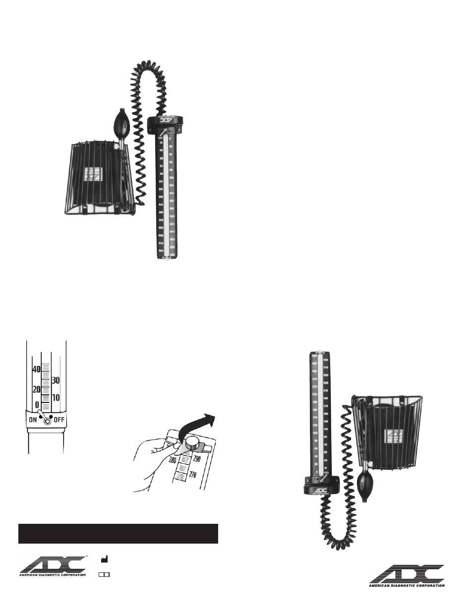
3.Position
the manometer
and bracket
and mount
to the
wall using
supplied
screws. T
ake care
not to
overtighten screws.
Position the
wall basket
as
shown in
the illustration
at right,
approximately 2”
to the
right of
the
manometer.
4.Using
a pencil,
mark the
3 holes
as before.
Repeat the
procedure for
drilling
the holes,
inserting anchors,
and mounting.
5.A
tta
ch
8
fo
ot
le
ng
th
o
f c
oil
ed
tu
bin
g t
o a
ir
in
le
t u
nd
ern
ea
th
m
ou
nti
ng
b
ra
ck
et.
Insert “male”
luer connector
on free
end of
coiled tubing
to “female”
luer
connector on
bladder tubing.
Wrap cuff
around bulb
and store
in the
basket.
Important: This
instrument is
designed to
permit wall
mounting without
first
disassembling main
unit from
its swivel
base/mounting bracket.
To
remove main
unit from
bracket, disconnect
tubing from
mounting bracket.
Unscrew wingnut
from bottom
of mounting
bracket, separating
main unit
from
bracket. Reverse
procedure to
reassemble.