AAF International Type N RotoClone User Manual
Page 3
3
Motor &
Drive
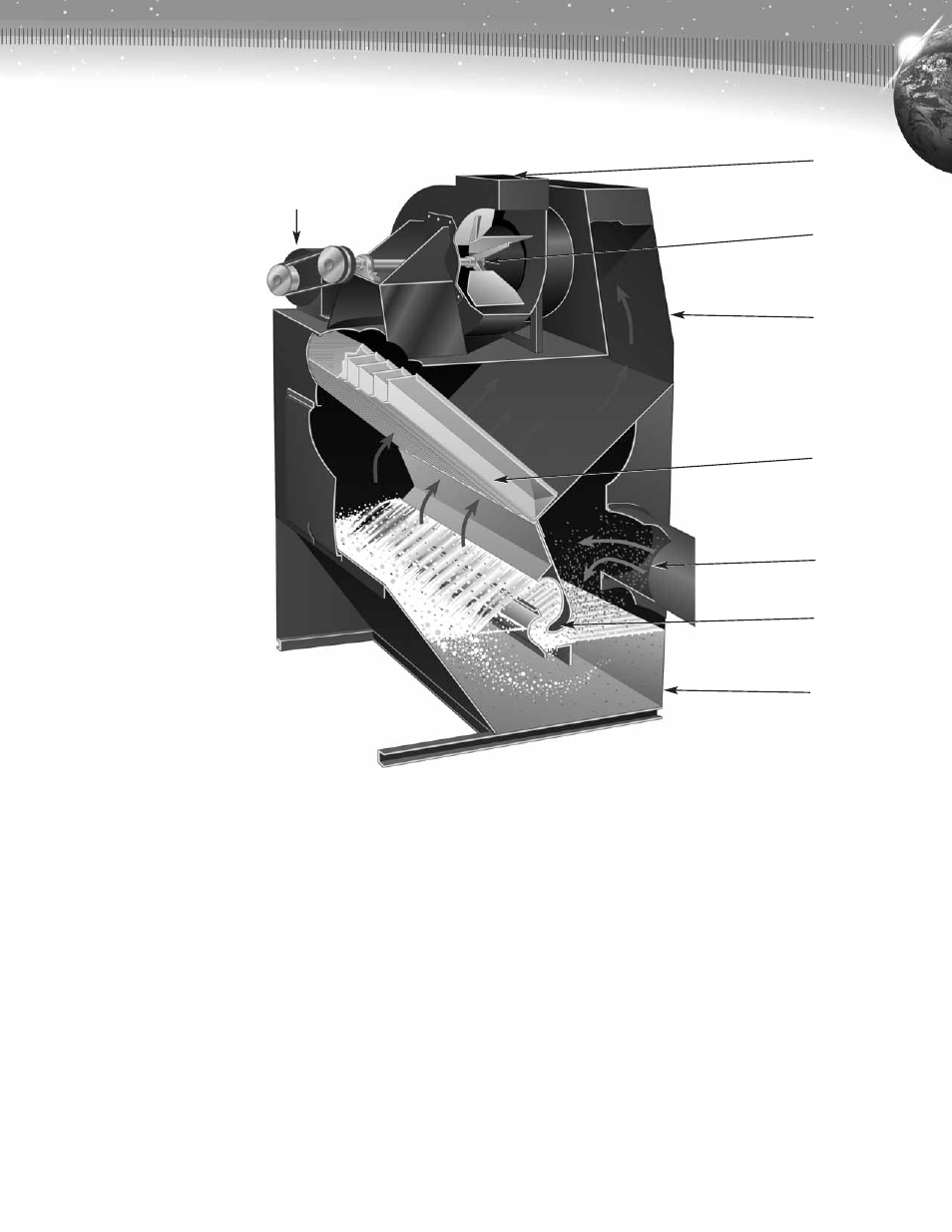
Figure 2. Cutaway section of typical Type N RotoClone Design 2 and 3 size 1
1
⁄
2
thru 6.
Clean Air
Discharge
Exhauster
Clean Air
Transition
Water
Eliminators
Dirty Air Inlet
Impellers
Hopper
3. For RotoClone Sizes 1
1
⁄
2
thru 6 which are not shipped with
exhausters or for all RotoClone Sizes 8 and larger, three-inch
sealing tape is furnished. This tape seals the
5
⁄
8
inch nominal gap
between the clean air transition and the exhauster inlet.
4. RotoClones, Sizes 8 thru 48 are shipped disassembled in major
subassemblies; RotoClone, clean air transition, motor, drive, and
exhauster. Necessary gasket material for the flange between the
RotoClone and transition section and the three-inch sealing tape
noted above are packed in a box with bolts.
5. If necessary, Sizes 16 thru 48 can be shipped with the collecting
section and hopper section disconnected.
Field assembly of collecting section and hopper section will require
the following:
a. Install gaskets on top of hopper external flange.
b. Set collecting section in place so its bolting flange matches
hopper flange. Lower carefully, watching for interference between
intermediate sheets (lower section of curved entrainment baffles)
and impellers. Walls of interior center section, formed by the two
intermediate sheets must be inside impeller bolting surface
(Figures 1 and 3).
c. Bolt outside flanges of collecting section and hopper section.
d. Bolt impellers to intermediate sheets. Before tightening, entering
edge (Figure 1) of impellers must be in a straight line. Impellers
were installed in the hopper section and aligned at the
factory. Each impeller section is matched-drilled with holes in
intermediate sheet. Pull these bolts tight and check alignment
before tightening remainder of bolts through slotted holes in
impellers and drilled holes in intermediate sheets.