AAF International Type N RotoClone User Manual
Page 13
13
(MAXIMUM
) OPERAT
ING LINE
#5
(MINIMUM)
OPERATI
NG LINE
#1
OPERATING
LINE #2
OPERATING
LINE #4
OPERATIN
G LINE #
3
12
11
10
9
8
7
6
5
600 700 800 900 1000 1100 1200
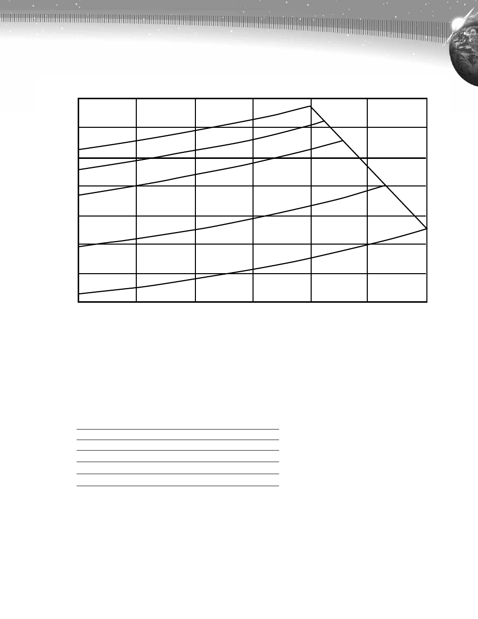
Figure 8. Typical chart of Type N RotoClone pressure loss for exhaust
volume variations and given operating lines. The Type N RotoClone
must operate on one of the operating lines. RotoClone size
multiplied by cfm./ft. impeller gives rating in cfm.
Flow Rate—cfm/ft. Impeller
Total Collector—Pressure Drop " w
.g.
Type N RotoClone Performance Curves
If further help is required there is an American Air Filter Representative available to check the operation of your RotoClone and
answer any questions concerning erection, operation, or maintenance.
Operating Line
1
2
3
4
5
Maximum Pressure Drop in. w.g.
7.5
9.0
10.6
11.2
11.7