0 foundations and anchoring, 0 ductwork and accessories, 0 electrical controls and wiring – AAF International OptiFlo Cartridge Collector User Manual
Page 4
4
3.0 Foundations and Anchoring
See Sales Drawings for anchor bolt location. Anchor bolts must
extend at least 1
3
⁄
4
" above foundation. The collector should be
located with consideration for emptying hopper, shortest run for
location of duct work, electrical and air connections and maintenance.
In the case of hazardous dust, consult local authorities for the location
of the unit.
WARNING: DO NOT DISCONNECT CRANE BEFORE TIGHTENING
ALL LEG, CROSSBRACING, AND ANCHOR BOLTS.
The OptiFlo dust collector is usually mounted on a reinforced concrete
foundation. However, roof mounting is also possible. When calculating
for foundation or roof mounting, the weight of the dust collector,
material collected, and all auxiliary equipment must be considered
together with snow, wind and seismic loads, See Individual
Specification Control Drawing for dust collector weight.
WARNING: Do not disconnect crane or attempt to support cabinet on
hoppers. Locations must be clear of all obstructions such as utility
lines or roof overhang (see specification control drawing), as a crane
must be used to move the collector into position.
4.0 Ductwork and Accessories
Connect the inlet duct to the inlet(s) above the access ports on the
collector, or to the top inlet. Connect the clean air duct (or manifold)
to outlet(s) located on the bottom and lower sides of the clean air
plenum. Ductwork should be of sufficient gauge to withstand the
system design pressure and should be independently supported.
The OptiFlo collector is not designed to support ductwork.
Attach hopper discharge device(s) per manufacturer’s instructions.
* Modules supplied with explosion vents are supplied with
additional installation drawings.
The hoppers are not designed for dust storage. A hopper discharge
device must be attached to the hopper in order to seal the system. A
hopper discharge air leak will result in improper operation of the unit.
WARNING: Potential shock hazard. Disconnect power before
servicing. Only qualified electrical personnel should work on
this system.
The OptiFlo pulse-jet cartridge collector is supplied with NEMA 4
electrical solenoids and pulse control (one control system per unit).
NEMA 9 option is available.
Control wiring must be field installed between the solenoid valves and
the pulse output terminals as shown on the electrical connection
diagram. If the optional factory wiring option has been purchased, the
solenoids are prewired to a junction box with terminal strip.
The pulse timer panel has a set of normally jumpered terminals,
labeled “pressure switch,” used only when an optional remote control
device (called demand pulse option) is used. The metal jumper is
removed and the “normally open” contacts of the optional pressure
switch are then connected to the “PS” terminals — see wiring diagram
provided with this option.
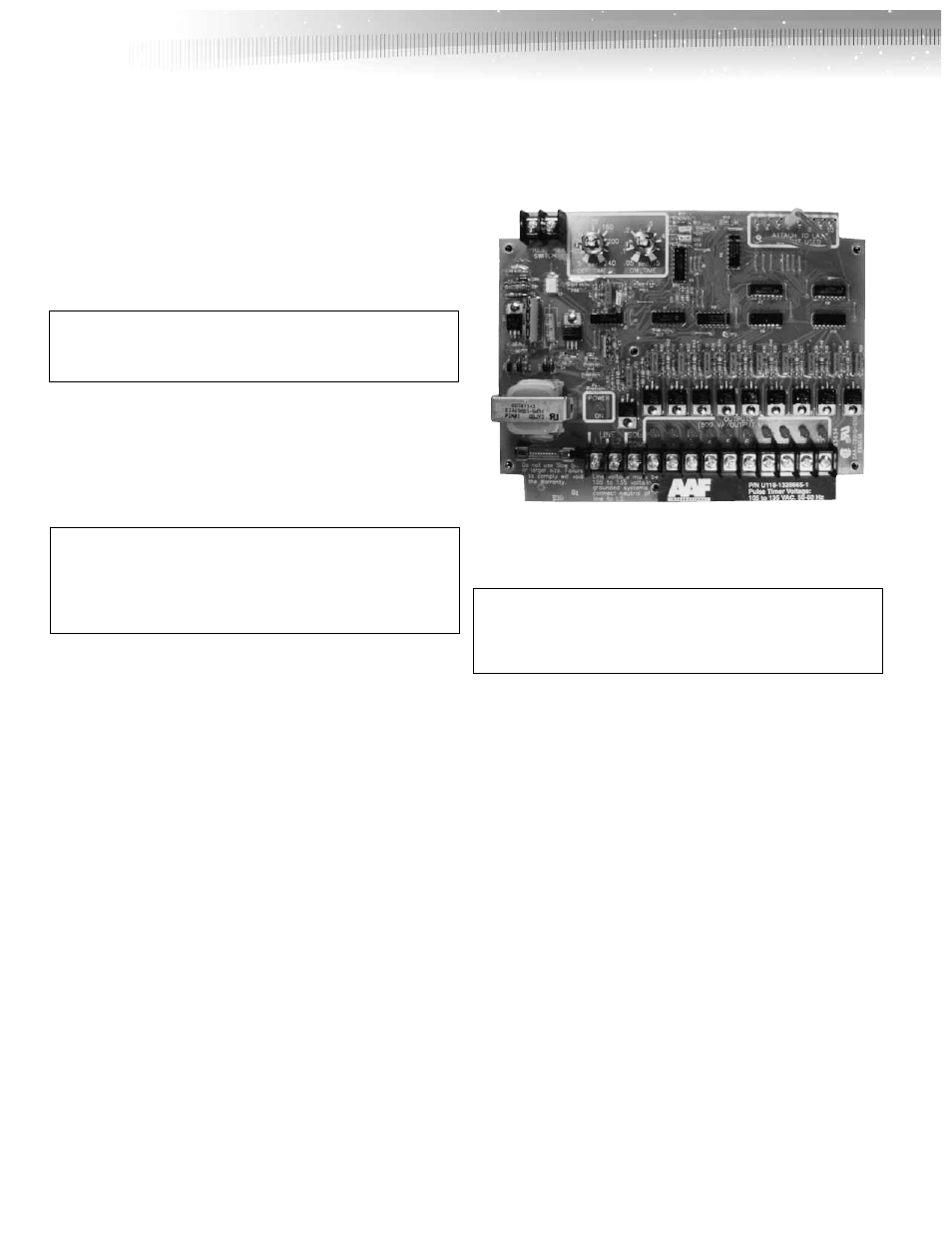
5.0 Electrical Controls and Wiring
Printed Circuit Program Timer Control