AAF International OptiFlo Cartridge Collector User Manual
Page 3
3
WARNING:
• Connect lifting sling to at least four cabinet lifting lugs -
distribute load equally.
• Connect lifting sling to double-thickness cabinet lifting lugs
provided on collectors 3 and 4 modules wide. Always use
spreader bars on collectors field assembled wider than
4 modules.
• Use clevices, not hooks, on lifting sling.
• Use of spreader bars is recommended on all lifting slings.
Attach legs — All legs are the same, however, they must be located in
the proper position as shown in Figure 3. Also, leg crossbracing must
be located as shown in Figure 3. Lift the entire cabinet/hopper
assembly and attach legs with bolts (included), flatwashers,
lockwashers, and nuts — do not tighten bolts. See Bolting Detail —
Legs to Cabinet, back page.
WARNING: Do not disconnect crane or attempt to support
cabinet on hoppers.
Attach leg crossbraces at rear of dust collector with included
5
⁄
8
"
bolts, flatwashers, lockwashers, and nuts. See Figure 3 and Bolting
Detail — Leg Crossbracing, back page – do not tighten bolts. Lift
the assembled unit onto foundation anchor bolts.
Tighten all leg and crossbracing bolts. Fasten unit down to
anchor bolts with flatwashers, lockwashers and nuts before
removing crane.
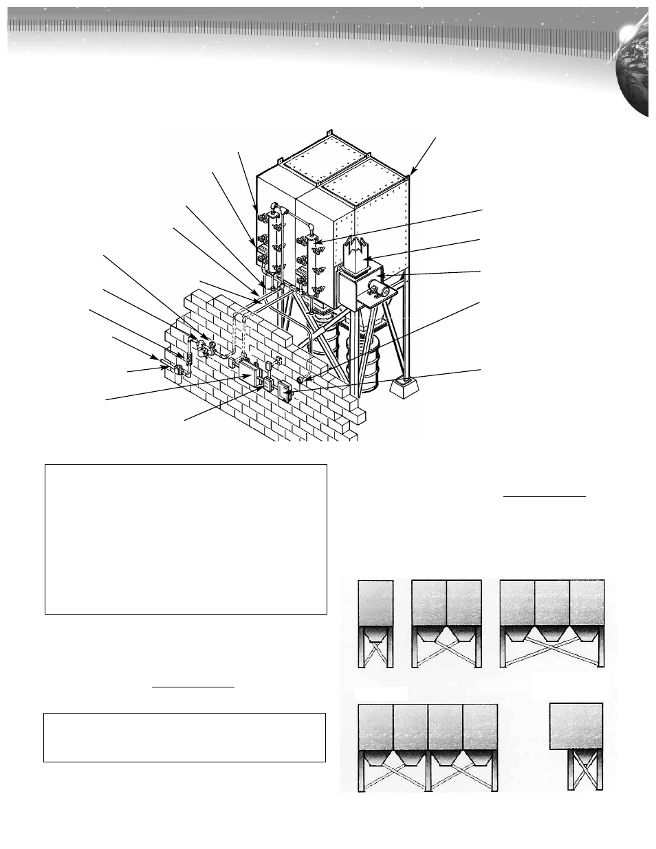
Figure 2. OptiFlo Cartridge Collector Typical Installation
Figure 3 - As viewed from the cartridge access side
1 MOD 2 MOD 3 MOD
4 MOD
Typical
Side View
Diaphragm
Valve
Solenoid
Enclosure
Air Header
Blow-Down Valve*
Air Line to
Manifolds*
Solenoid
Electrical
Connection*
Air Regulator*
Air Filter
(Bleed Type)*
Air Valve*
Air Supply Line*
Automatic
Condensate Valve*
Solid-State
Control Timer
Low Voltage (120 V AC) Magnetic
Starter (Blower Motor)*
Lifting Lug
Air Manifold
Collector Fan Outlet*
Fan (Optional)
Magnehelic Gauge
Power Supply Disconnect Switch*
NOTE: These (*) items are not included with Dust Collector.