Installation (between joists mounting) continued, Caution, Lighting unit position – Panasonic FV-08VRL1 User Manual
Page 6
Attention! The text in this document has been recognized automatically. To view the original document, you can use the "Original mode".
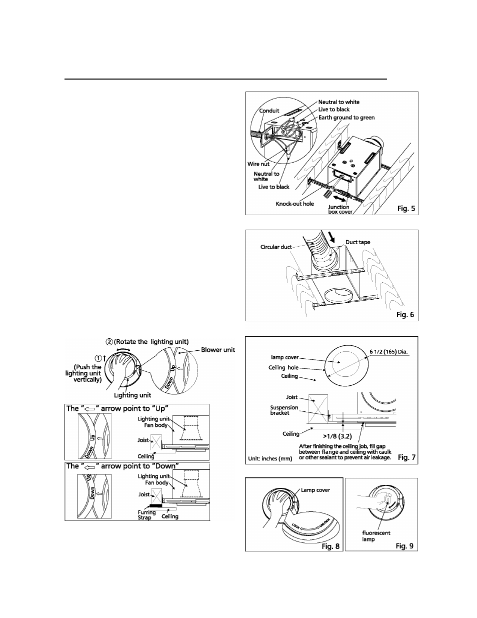
7. Remove the knock-out hole from the junction
box cover, and remove the junction box cover.
Then secure the conduit or stress relief to the
junction box knock-out hole. (Fig. 5)
8. Refer to wiring diagram (Page 4).
Follow all the local electrical safety codes as well
as the National Electrical Code (NEC).
Using UL approved wire nuts, connect house
power wire to ventilating fan wires. (Fig.5)
INSTALLATION (BETWEEN JOISTS MOUNTING) CONTINUED
CAUTION:
Mount junction box cover carefully so that lead
wires are not pinched.
9. Install a circular duct and secure it with clamps
or wire ties, and seal it with mastic or approved
duct tape. A 4-inch circular duct or 6-inch circular
duct is needed to connect to the relevant part of
adaptor. (Fig. 6)
10. Finish ceiling work.
A circle ceiling hole ( 6 1/2 inches (165mm) dia.)
should be cut. And make sure there will be
a gap (>1/8 inches (3.2mm )) between bottom of
fan body and ceiling. (Fig. 7)
11. Unlock the lamp cover.(Fig.8)
LIGHTING UNIT POSITION
The lighting unit position is adjustable in the range of
1/2 inches (12.7mm). The "Up" position (the factory
setting) is recommended for normal installation.
In case of Furring Strap Joist installation, the "Down"
position is acceptable.
Do the following to adjust the lighting unit:
Caution:
Failure to follow the above method may result in
poor performance.
12. Install the fluorescent lamp. (Fig. 9)
6