Compressor terminal box, D gb f e, Fig. 21 – GEA Bock HG34e A User Manual
Page 16
16
D
GB
F
E
96191-11.2014-DGbFE
R1
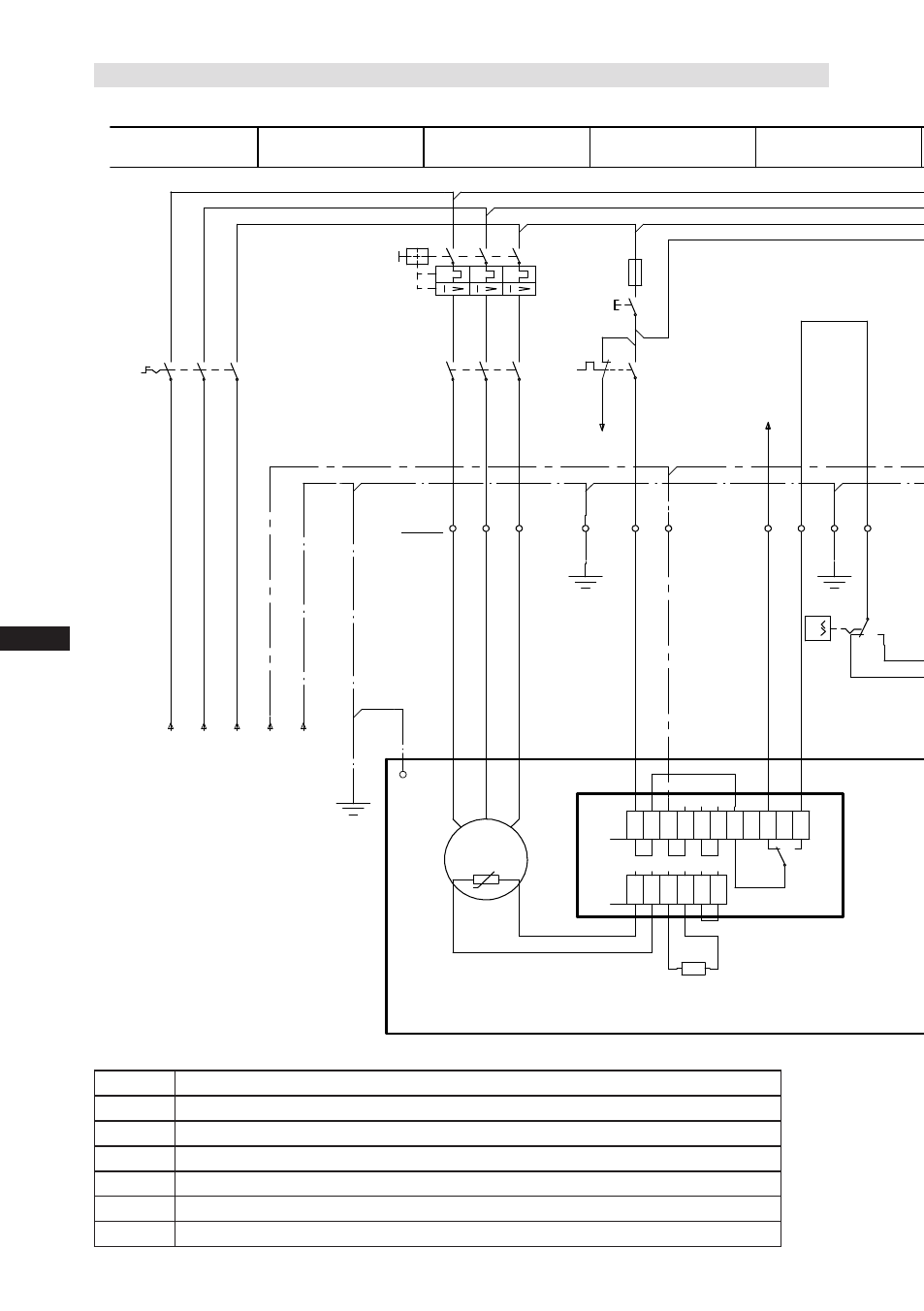
Cold conductor (PTC sensor) motor winding
R2
Thermal protection thermostat (PTC sensor)
F1
Load circuit safety switches
F2
Control power circuit fuse
F3
Safety chain (high/low pressure monitoring)
B1
Release switch (thermostat/pressostat)
Q1
Main switch
5.3 Circuit diagram for direct start 230 V
∆ / 400 V Y
Fig. 21
Compressor terminal box
See also other documents in the category GEA Bock Air equipment:
- HG5 (32 pages)
- HG7 (34 pages)
- HG4 (32 pages)
- HG6 (32 pages)
- HG8 (38 pages)
- HG34e (30 pages)
- HG22Р (26 pages)
- HG12Р (26 pages)
- BCM2000 (18 pages)
- HG22e (26 pages)
- HG34P (26 pages)
- HG88e (38 pages)
- HG44e (34 pages)
- HА4 (32 pages)
- HА34P (26 pages)
- HA12P (26 pages)
- HA5 (32 pages)
- HA6 (32 pages)
- HG22Р CO2 (28 pages)
- HG34P CO2 (28 pages)
- HG4 CO2 (30 pages)
- HG12Р CO2 (28 pages)
- HG12e CO2 (28 pages)
- HGX2 CO2 T (28 pages)
- HGX34 CO2 T (40 pages)
- HGX46 CO2 T (40 pages)
- HAX2 CO2 T (28 pages)
- HG5 R134a (32 pages)
- HG6 R134a (32 pages)
- HG7 R134a (32 pages)
- HG4 R134a (32 pages)
- HGZ7 (42 pages)
- F (44 pages)
- F18 (28 pages)
- FK40 (26 pages)
- FK30 (26 pages)
- FK50 (26 pages)
- FK20 (26 pages)
- HG22P A (28 pages)
- HG22e A (28 pages)
- HGX34P 2 pole (32 pages)