8| technical data – GEA Bock HG7 R134a User Manual
Page 27
D
GB
F
E
27
96182-01.2015-DGbFEI
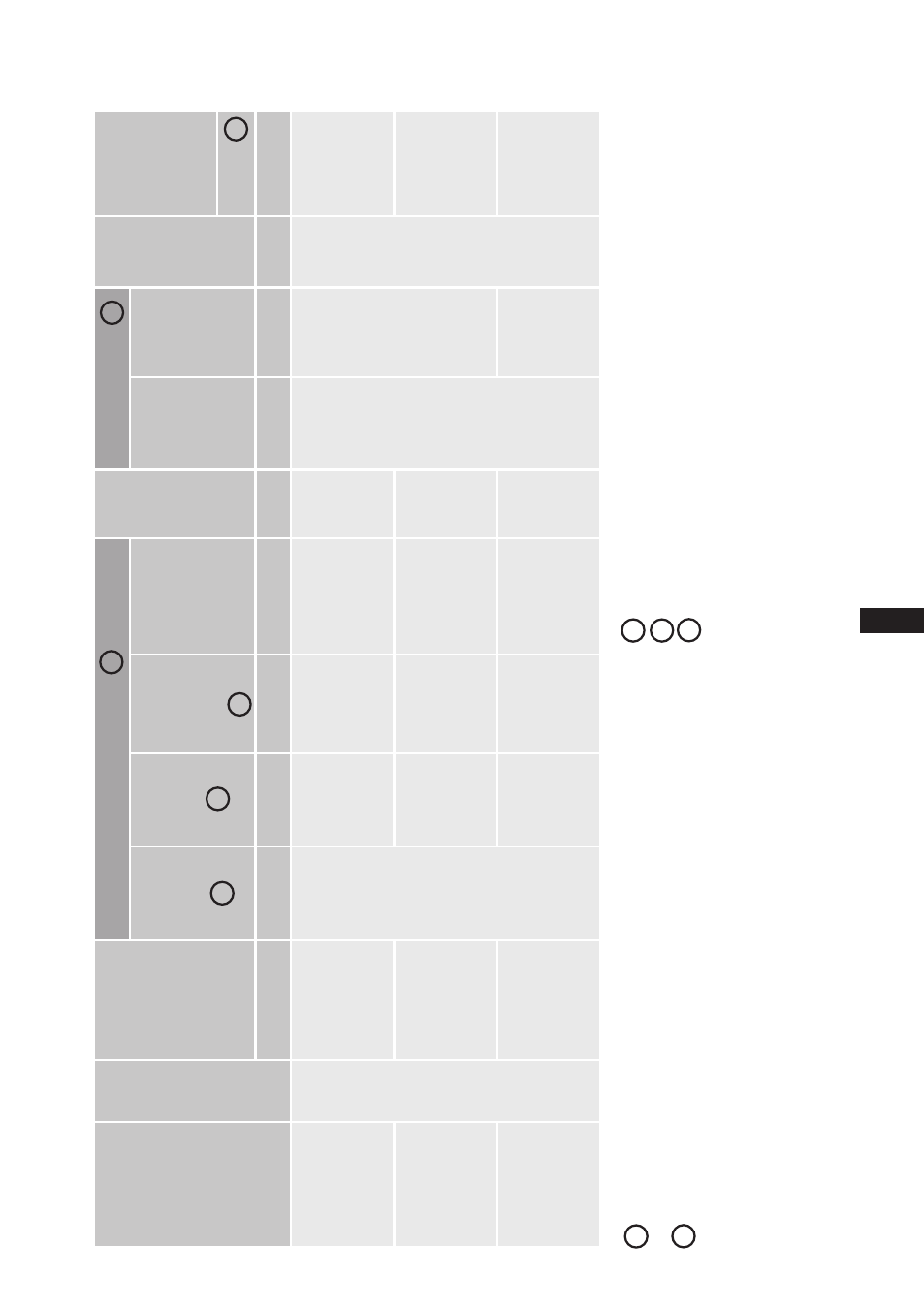
8| Technical data
Ty
pe
No. of cylinders
Displacement
50 / 6
0 H
z
(1
45
0
/ 1
74
0
rp
m)
Electrical data
W
eight
Co
nnec
tio
ns
Oil charge
Sound
pressure
level
Voltage
Max.
Operating current
PW 1 + 2
Max.
power
consump
-
tion
Starting
current
(rotor
locked)
PW 1 / P
W 1 + 2
Dis
-
charge
line DV
Suction
line SV
m
3
/h
A
kW
A
kg
mm
(
in
ch
)
mm
(
in
ch
)
Lt
r.
dB
(A
)
HG
X7/
16
20
-4
R13
4a
6
14
0,
6 / 1
68
,8
63
34
,1
22
3 / 3
40
278
42 (
1
5
/
8
)
54 (
2
1
/
8
)
4,
5
78 / 7
8 / 7
7
HG
X7/
18
60
-4
R13
4a
16
1,4 / 1
93
,7
68
39,2
26
8 / 3
73
296
79 / 7
9 / 7
8
HG
X7
/2
11
0-
4
R13
4a
18
3,
6 / 2
20
,4
81
44,6
29
1 / 4
29
289
64 (
2
5
/
8
)
80 / 8
0 / 7
9
1
2
3
2
4
380-420 V
Δ/YYY - 3 - 50 Hz PW
440-480 V
Δ/YYY - 3 - 60 Hz PW
PW = Part Winding
Winding ratio
: 60% / 40%
L / M / H
5
Tolerance (± 10%) rela
tive to the mean value of the volta
ge range.
Other
volta
ges
and
types
of
current
on
request.
-
Th
e
sp
ec
ifi
ca
tio
ns
fo
r ma
x.
p
ow
er
c
on
su
m
pt
io
n
ap
pl
y
fo
r 5
0H
z
op
er
at
io
n.
Fo
r 6
0H
z
op
er
at
io
n,
th
e
sp
ec
ifi
ca
tio
ns
h
av
e
to
b
e
m
ul
tip
lie
d
by
th
e
fa
ct
or
1.
2. T
he ma
x. w
or
kin
g c
ur
re
nt r
ema
in
s u
nc
ha
ng
ed
.
-
Take account of the max.
opera
ting current / max.
po
wer consumption for
design of fuses,
supply lines and safety devices.
Fuse:
Consumption
ca
tegor
y AC3
1
2
All
specifica
tions
are
based
on
the
a
vera
ge
of
the
volta
ge
range
For solder connections
L = lo
w tempera
ture (-35 / 40 °C),
M
= normal cooling (-10 / 45
°C),
H = air conditioning (5 / 50°C)
sound pressure level measured in
lo
w
reflection
measuring
area,
measuring
distance
1m.
Compressor opera
tion a
t 50 Hz (1450 rpm),
refrigerant R404A.
Values
sta
ted
are
a
vera
ge
values,
tolerance
±
2
dB(A).
5
3
4