Building instructions, Step14 – Erica Synths DIY Polivoks(ish) ADSR EG kit User Manual
Page 14
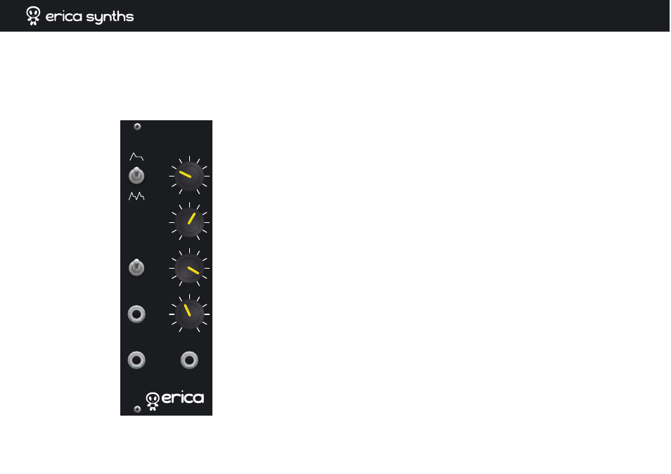
SUS
TAIN
DECAY
RELE
ASE
ATTACK
GATE
EG OUT
HARD
GATE
TRIGGER
POLIVOKS ADSR
BUILDING INSTRUCTIONS
step14
Install pot knobs! Congratulations! You have completed Erica Synths
ADSR envelope generator!
TRIMMING AND TROUBLESHOOTING
ſter supplying power to the EG module, connect the voltmeter to the washers of
trimming resistors VR1 and VR2 and check, if they allow tuning from -10V to +10v.
If not, there is something wrong with the assembly or power supplies. Set both
inputs to +2.5V for most general compatibility: at this setting, trig and gate control
voltages below this voltage will be considered low level, and when above - high. This
allows EG to work with +4v, +5v logic and 10V control signals, with inactive state
anywhere below 2V down to -10V. If your control source has different output
voltages, feel free to set it anywhere in the middle of its span. Say, if your controller
outputs -7 when idle and -4 when active, set the respective trim resistor to -5.5V.
Basically, you have to achieve the situation, when both Gate and Trigger signals
affect the envelope.
If you wish to modify ADR time, feel free to experiment with value of C3!
WHAT TO DO IF EG DOESN'T SEEM TO BE WORKING.
Ensure that input signals that you supply to the module are good and knobs are set
to meaningful values. Check external voltage supplies and onboard -10V and +10V
as well as +5V LDOs. Tune the gate and trig input threshold pots. Using an
oscilloscope, check if trig and gate signals from controller appear on respective
schmitt trigger (74HC14) gate inputs and outputs. If so far all seems well, check to
see if rotating knobs produce control voltages on the respective multiplexer input
pins. When in idle state, analog multiplexer outputs should match the idle voltage
and release knob voltages on inputs. If they don't, check if multiplexer selection
signals are all low (when in idle). If they are not, there is something wrong with the
control logic or control signals. Check if low voltage (slowest setting) for the rate
knobs is somewhere around -0.65V. If not, there may be something wrong with the
reference source circuit (OP1.1 and R1, D1, C1, R2, R3) that supplies this voltage.
Changing release rate in idle state should change voltages at the diodes D2 and D3.
Voltages from OP1.2 and OP3.1 should change in a mirror fashion, accordingly to the
set rate. At the slowest rate cathode of D3 should be around -0.65V while anode of
D2 should be around +0.65V. Increasing the rate speed should increase voltage on
the cathode of D3 and decrease in on anode of D2.
User manual by Girts Ozolins@Erica Synths. Design by Edgars Rasins. Copying, distribution or any
commercial use of schematics, technical solutions and/or parts of the manual in any way is prohibited
and needs the written permission by Erica Synths. Specifications are subject to change without notice.