Jp1 jp2a jp2b jp1 – Doepfer Dark Link USB/Midi to CV/Gate Interface User Manual
Page 16
Dark link
DOEPFER
Nuts‘n bolts of MIDI-CV/Gate conversion
16
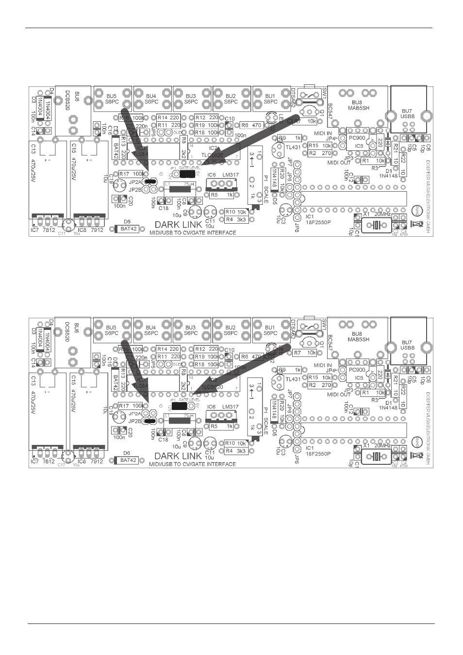
JP1 position for 5 Volts gate signal (middle and rightmost contacts – default setting)
JP2 position for CV2 range -2,5V to +2,5V (set to JP2A – default setting)
JP1 position for 12 Volts trigger (middle and leftmost contacts)
JP2 position for CV2 range 0V to +5V (set to JP2B)
To generate a switch trigger, the jumper (JP1) has to be taken off.
Please note that it is necessary to invert the trigger polarity when generating a switch trigger.
Please refer to page 12, note (4).
JP1
JP2A
JP2B
JP1