Dark time doepfer, Functions – Doepfer Dark Time Sequencer User Manual
Page 11
Functions
Dark time
DOEPFER
11
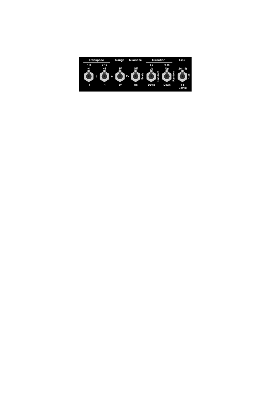
3.1.3. Sequence Control
The sequence control functions allow control over the previously programmed sequence. They determine
or alter pitch and / or the playback order of the step registers.
•
Transpose
With these switches you can transpose both registers of the sequence up or down by one octave.
The switch on the left addresses steps 1 – 8, the switch on the right addresses steps 9 – 16.
•
Range
This switch determines the control voltage range and thus the pitch range that is covered by one
entire turn of a step control. You may select between 1 Volt, 2 Volts and 5 Volts. If the synthesizer
connected works with a control scaling of 1V/octave, these voltages are equivalent to a range of
one, two, or five octaves.
•
Quantize
When this switch is set to ”Off”, the step controls will be almost continuously variable within the
range determined by the ”Range” switch. We use the term ’almost’ since it is still stepped digitally,
but into 1024 very small increments which are – in effect – continuous and barely noticeable.
Set to ”On”, the control voltage range gets scaled. That means, it is sliced into discrete steps that
are equivalents of musical semitones. The number of chromatic steps, i. e. semitones that are
covered by one entire turn of a step control is again determined by the setting of the ”Range” switch.
When set to ”1V”, the step controls are quantized into 13 discrete semitones (one octave, or – to be
more precise – a ”ninth” interval; e.g. ”c” to ”C”). ”2V” means 25 semitones (two octaves) and ”5V”
means 61 semitones (five octaves).
”Scale” will be used for future updates. Stay tuned.
You will find some information and additional ideas dealing with this topic in chapter 4, “Nuts and
bolts of analog sequencing“, and in section 4.2.2., ” Programming melodies into the step sequencer”
on page 24.
•
Direction
Use these switches to determine the playback order for both step registers independently. The
left-hand switch addresses steps 1 – 8, the right-hand switch addresses steps 9 – 16. In ”Up”
position, the respective register will run forward, in ”Down” position backward. ”Random” will
address steps in random order (would you have guessed?).
•
Link
Use these switches to run both step registers in parallel (”2x(1-8)”) or serial (”1-16”) mode. ”2x(1-8)”
will generate two sequences of eight steps maximum, running in parallel, ”1-16” will generate one
sequence of 16 steps maximum.
”Custom” allows the programming of individual gate time settings for each of the steps of the upper
register.
You will find a detailed description in section 3.1.5. ”Individual Gate LengthTime for Steps 1 – 8” on
page 14.