Using the hydraulic lock lever, Regenerative system – Cub Cadet Ex2900 User Manual
Page 73
Ex2900 / 3200 Operator's Manual
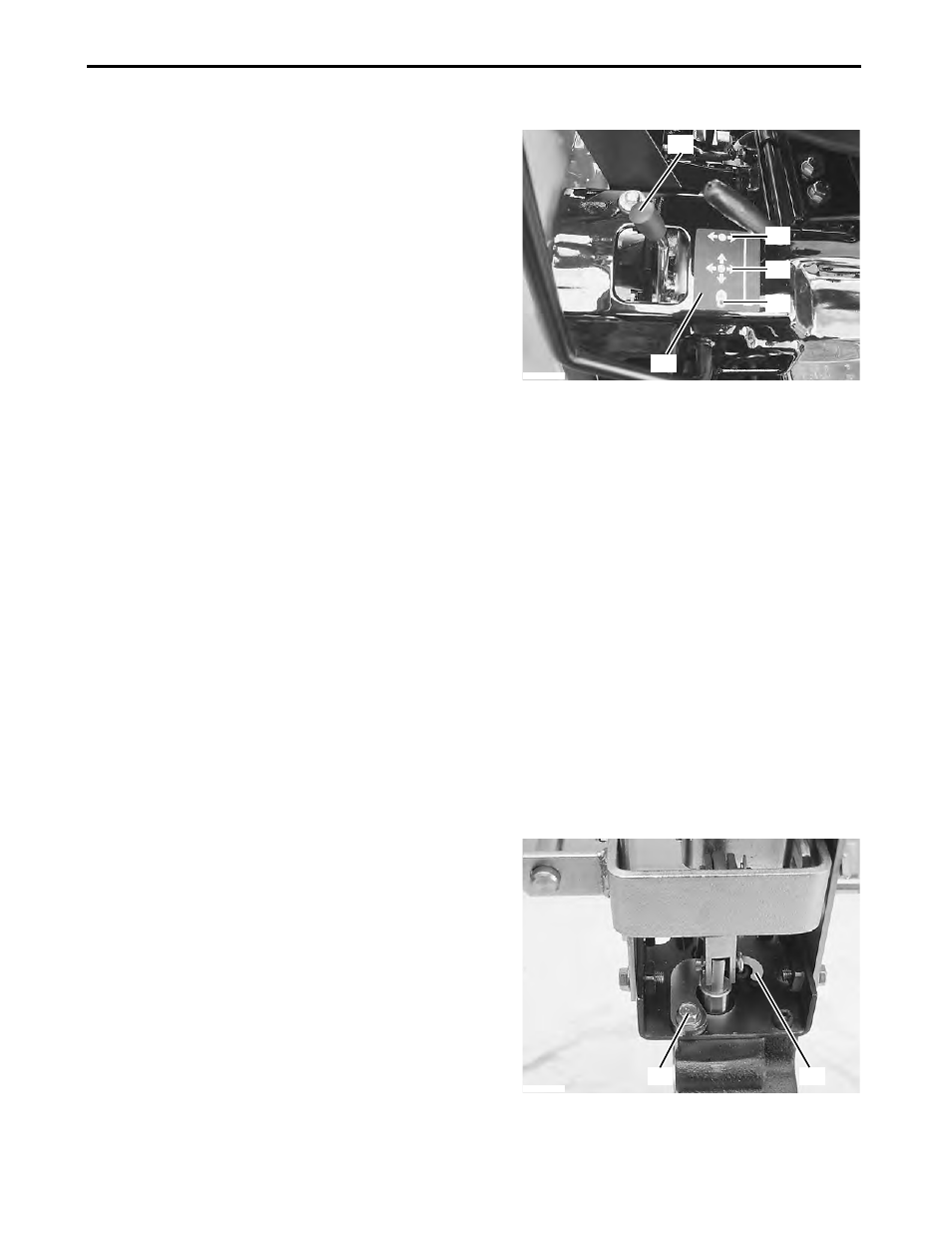
1. Using the Hydraulic Lock Lever
Use the hydraulic lock lever to adjust the shift direction of
the implement control lever in accordance with particular
operating conditions or situations.
(A) Hydraulic lock lever
(B) Shift pattern decal
(1) To limit the implement control lever to the right-left
movement:
Pull the lock lever outward (rightward), and then fully
rearward as shown on the attached shift pattern.
(2) To allow the movement of the implement control lever
in all the directions: Move the lock lever to the center
position as shown on the shift pattern decal.
(3) To prevent the movement of the implement control
lever in all the directions: Move the lock lever fully
forward as shown on the shift pattern decal.
IMPORTANT: Avoid damage.
●When the movement of the implement control lever is
limited by the hydraulic lock lever, do not forcibly move
the implement control lever in any direction other than its
allowable direction.
2. Regenerative System
■ Using the Implement Control Valve Regenerative Circuit
The implement control valve has a built-in regenerative
circuit. “Regenerative” means that pressure is applied to
both sides of the implement control valve cylinder.
The implement control valve can be adjusted to the
“regenerative” position to allow the implements such as
loaders to dump the bucket faster.
1. Remove the screw and lockout plate situated
immediately below the implement control lever and
rock shaft control lever.
(A) Screw
(B) Lockout plate
2. Turn over the lockout plate and install the screw as
shown in the photo.
3. Tighten the screw.
P3013707
(A)
(B)
(1)
(2)
(3)
P3013749
(A)
(B)
Lock in position