Cub Cadet GT-2554 User Manual
Page 32
32
SECTION V. MOWER DECK
A. INSTALLATION AND REMOVAL OF DECK
INSTALLATION OF DECK
WARNING: Before performing the mower
deck installation, place the PTO switch in
the “OFF” position, engage the parking
brake, turn the ignition key to the “OFF”
position and remove the key from the
switch. Disconnect the spark plug wires
for additional safety. When handling the
mower deck, be careful not to cut your-
self on the sharp blades.
1.
Position the tractor and mower deck on a firm,
level surface.
2.
To aid in sliding the deck under the tractor, repo-
sition all four ball wheels as shown in Figure 27.
To reposition the rear wheels; remove the quick
pins, rotate the rear wheels 90°, and raise them
to their uppermost position in the castor chan-
nels. Install the two quick pins in the rear holes of
the castor channels to secure the rear wheels in
this position. Temporarily remove the quick pins
and rotate the front castor assemblies outward.
The deck should be in its lowest position.
Figure 27
3.
Position the deck on the right side of the tractor
with the front of the deck facing toward the front of
the tractor (Refer to Figure 28).
NOTE: To aid in sliding the deck under the tractor, turn
the steering wheel fully to the left, then back to the
right as you maneuver the deck under the tractor.
Figure 28
WARNING: To avoid possible equipment
damage, make sure that the tractor
implement lift handle is raised to its
highest setting before sliding the deck
under the tractor.
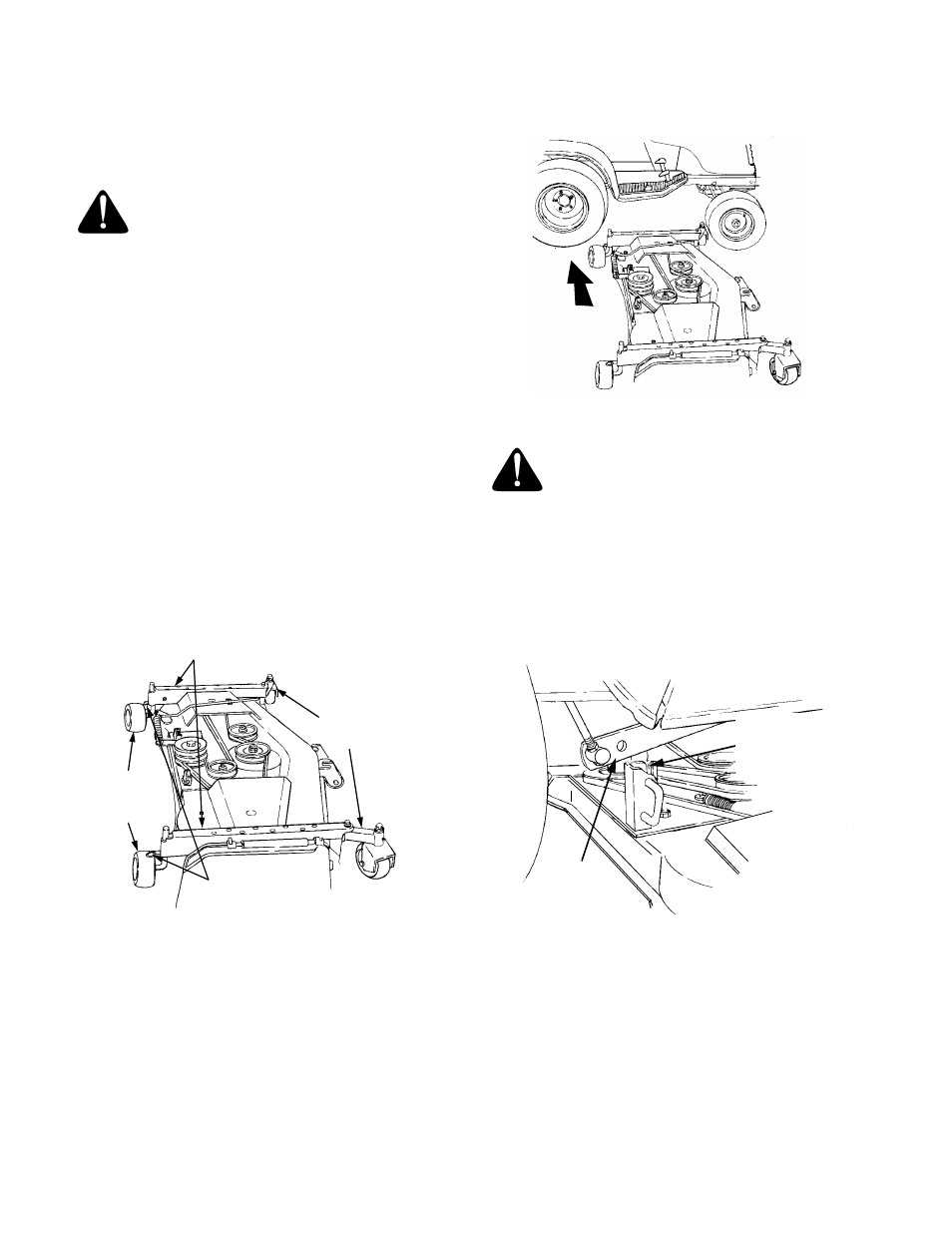
4.
Raise the tractor implement lift handle to its
highest setting and slide the deck under the
tractor. Make sure the slot in each rear deck
bracket aligns with the implement lift link on each
side of the tractor (See Figure 29).
Figure 29
5.
Reposition all four wheels in their original position
and secure with the quick pins. Turn the steering
wheel so that the tractor front tires are straight.
NOTE: If installing the deck on a new tractor, the
front lift rod/bracket assembly is already installed on
the front of the tractor. Cut the cable tie used to hold
the front lift rod up to the tractor frame during shipment,
then proceed to step 7.
FRONT CASTOR
CASTOR CHANNELS
REAR
BALL
WHEELS
QUICK PINS
ASSEMBLIES
SLIDE
UNDER
IMPLEMENT
LIFT LINK
(BOTH SIDES)
SLOT IN REAR
DECK BRACKET
(BOTH SIDES)