Cub Cadet CC 500 BAT User Manual
Page 16
ELECTRICAL SYSTEM
12
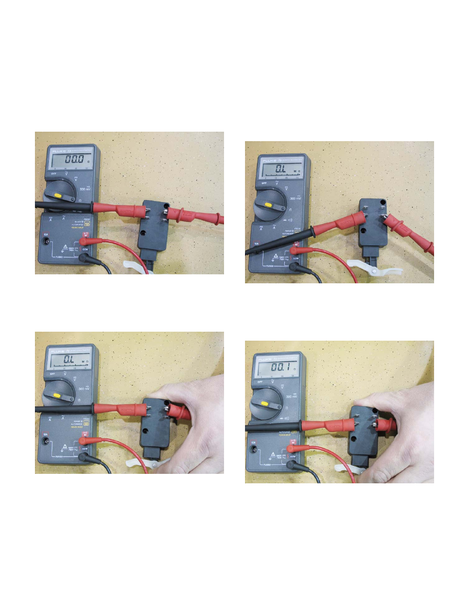
2c. Circuit 1 is a normally closed circuit. That
means there should be continuity through
that circuit when the switch is at rest.
2d. To test that part of the switch, attach a
DVOM to the circuit. Set the meter to the
Ohms or “
Ω
”
scale. The meter should
read zero ohms. See Figure 2.22.
2e. With the DVOM still attached, press in the
switch. The meter should read infinity.
See Figure 2.23.
2f. Circuit 2 is a normally open circuit. That
means there should not be continuity
through that circuit when the switch is at
rest.
2g. To test that part of the switch, attach a
DVOM to the circuit. Set the meter to the
Ohms or “
Ω” scale
.
The meter should
read infinity. See Figure 2.24.
2h. With the DVOM still attached, press in the
switch. The meter should read zero or
near zero resistance. See Figure 2.25.
2i. If the switch has any reading different than
what is described above, replace the
switch.
2j. Reconnect the wires to the switch. Make
sure the wires are attached to the proper
terminals.
Figure 2.22
Figure 2.23
Figure 2.24
Figure 2.25