Cub Cadet i1050 User Manual
Page 24
4
s
ectiOn
7— s
ervice
10. While holding the front deck hanger rod upward until it clears
the hanger bracket on the front of the deck, carefully slide the
deck out from the right side of the tractor.
Cutting Blades
WARNING: Be sure to shut the engine off,
remove ignition key, disconnect the spark plug
wire(s) to prevent unintended starting before
removing the cutting blade(s) for sharpening or
replacement. Protect your hands by using heavy
gloves or a rag to grasp the cutting blade.
WARNING: Periodically inspect the blade
spindles for cracks or damage, especially if you
strike a foreign object. Replace immediately if
damaged
The blades may be removed as follows.
Remove the deck from beneath the tractor, (refer to
Cutting Deck Removal) then gently flip the deck over to
expose its underside.
NOTE: A block of wood may be placed between the deck
housing and the cutting edge of the blade to help in
breaking loose the hex nut securing the blade.
Use a 15/16" wrench to loosen the hex flange nut securing
the blade to the bottom of the spindle assembly. Secure
the spindle by either holding the blade tightly, or by using
a second wrench to hold the nut at the top of the spindle.
Continue holding the blade onto the star hub of the
spindle, and remove the flange nut and cutting blade.
Repeat the previous steps to remove the other blades.
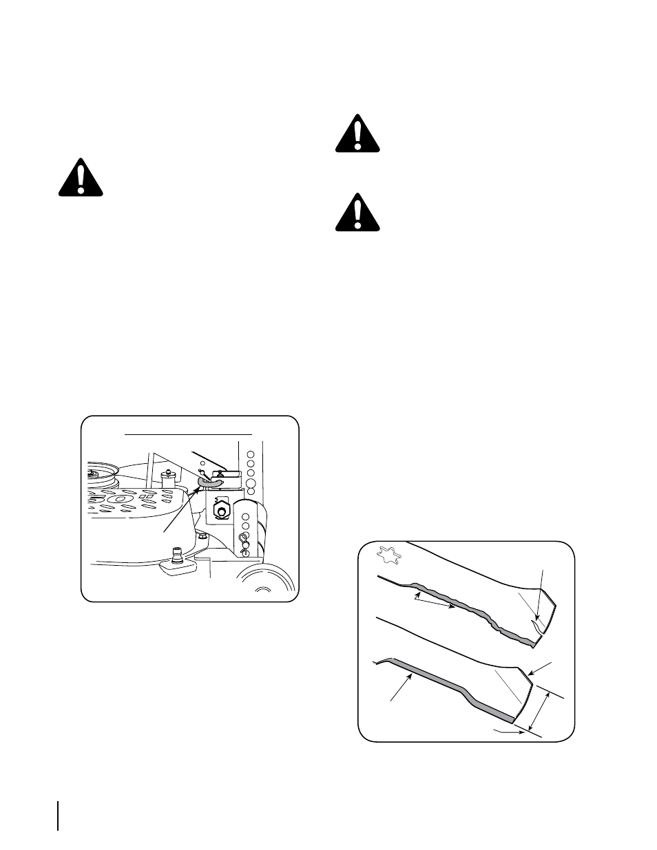
To properly sharpen the cutting blades, remove equal
amounts of metal from both ends of the blades along
the cutting edges, parallel to the trailing edge, at a 25°
to 30° angle.
IMPORTANT: If the cutting edge of the blade has already
been sharpened to within 1 5/8” from the edge, or if any
metal separation is present, replace the blades with new
ones. See Figure 7-2.
Figure 7-2
•
•
•
•
•
1-5/8 inch
Blade Separation
Worn Blade
Edge
Sharpen Edge
Evenly
Wind Wing
IMPORTANT: Never jump your tractor’s dead battery with
the battery of a running vehicle.
Connect end of one jumper cable to the positive
terminal of the good battery, then the other end to the
positive terminal of the dead battery.
Connect the other jumper cable to the negative termi-
nal of the good battery, then to the frame of the unit
with the dead battery.
WARNING!: Failure to use this procedure could
cause sparking, and the gas in either battery
could explode.
Cutting Deck Removal
To remove the cutting deck, proceed as follows:
Disengage the PTO (Blade Engage) and engage the
parking brake.
Place the deck gauge wheels in their highest setting
(lowest deck setting).
Lower the deck by moving the deck lift lever into the
bottom notch on the right fender.
Looking at the cutting deck from the left side of the
tractor, locate the deck support pin on the rear left side
of the deck. Refer to Figure 7-1.
Pull the deck support pin outward to release the deck
from the deck lift arm. Pivot the support pin handle
downward to lock the pin in the disengaged position.
Refer to Figure 7-1.
Figure 7-1
Move to the right side of the tractor and repeat the
previous step to release the deck from the RH lift arm.
Move the deck lift lever into the top notch on the right
fender to raise deck lift arms up and out of the way.
Carefully slide the cutting deck forward and remove the deck
belt from around the tractor’s PTO pulley on the bottom of the
engine.
9. Continue to roll the deck toward the front of the tractor until
the front deck hanger rod can be removed from the slots of the
hanger bracket at the front of the deck.
1.
2.
1.
2.
3.
4.
5.
6.
6.
50" Mower Deck Shown
Deck Support
Pin