Checkline LS-SCU User Manual
Page 5
- 5 -
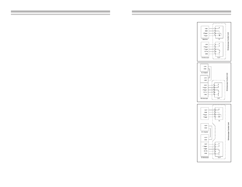
Fig 4. Trigger signal and power supply
from external installation.
Fig. 5 Trigger signal from this
instrument. Power supply from
the stroboscope (optional).
Fig. 6 Trigger signal from sensor
(optional), power supply for this
instrument from stroboscope
(optional). Sensor power supply
via this instrument.
The power can be supplied either via the
instrument’s power supply unit (available
as an option) or via the installation under
observation.
- 8 -
5.3
Units (see diagram on page 6)
0
8 FPM: Flashes per minute.
0
9 1/min: Rotations per minute.
10 Hz: Frequency of movement per second.
5.4 Operating
Notes
(see diagram on page 6)
12 RANGE: External trigger signal out of range 13 EXT External
trigger signal selected.
14 INT: Flash frequency generated by instrument.
NOTE: Any parameter deviating from the default setting will blink
during operation.
NOTE: In external trigger signal operation, the display will be in these
units: 1/min (instead of FPM) or Hz.