Checkline LS-SCU User Manual
Page 4
- 4 -
4.0 A
SSEMBLY AND
C
ONNECTION
The power can be supplied either via the installation under observation or the
stroboscope’s own power supply. Alternatively, power can be supplied via a
power supply unit (optional).
The function of the stroboscope control unit is to control a stroboscope.
In addition, it can be used to influence an incoming trigger signal from an
external system.
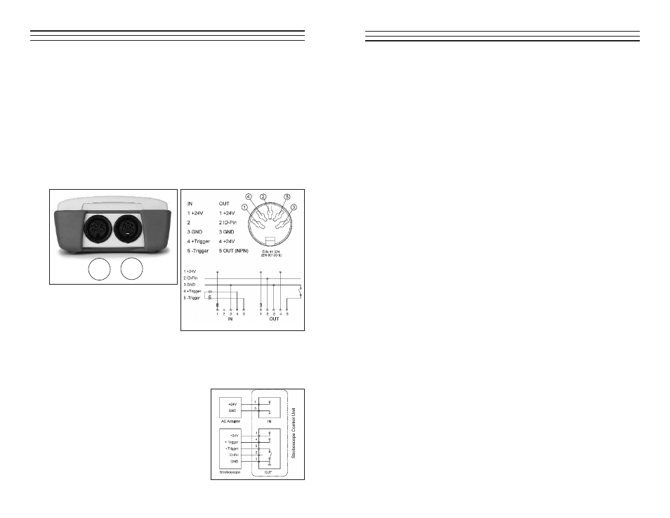
This device has two jacks. Power can be supplied via either of these jacks. The
jack for trigger input from an external system or sensor is labeled IN. The jack
for trigger output to a stroboscope is labeled OUT. The position of the jacks is
indicated in (Fig. 1). The wiring of the connectors is shown in (Fig. 2)
4.1 Typical
Wiring
Options
Please see Figs. 3-6 for examples of wiring options. Please note that
you need optional accessories for the examples (such as an stationary
stroboscope, power supply unit or sensor).
Fig 3. Trigger signal from this
instrument. Power supply
from the power supply
unit (optional).
IN
OUT
Fig.1
Fig. 2
- 9 -
6.0 H
INTS AND
S
UGGESTIONS
Problem:
The trigger signal is generated before the required observation
point.
Result:
The stroboscope flashes too early.
Solution:
Set a time delay between the input and output signals in ms
steps until the stroboscope delivers the required view.
Problem:
Your equipment is consistently transmitting the trigger signal
before location to be observed. However, your equipment runs at
different speeds.
Result:
Your stroboscope flashes at different locations, some of which
are unusable.
Solution:
Use phase shift (in degrees) to permanently shift the flash
position. The stroboscope will now adapt automatically to
changing speeds and will flash at a location which is shifted by
the set angle.
Problem:
An external trigger (e.g. a sensor) is monitoring a gear-wheel. Its
frequency is many times greater than the required flash frequency.
Result:
You don't receive the required control image.
Solution:
Instead of using each input signal, the impulse divider only
triggers a flash impulse after every 10th, 25th or 255th input
signal. Set the value in key steps or in "continuous flow" mode
until the required result is displayed.
Problem:
You need measurement values to be displayed in a variety
of formats.
Solution:
You have the following options: the instrument can display
FPM, RPM or Hz.