Aviom SB4 User Manual
Page 22
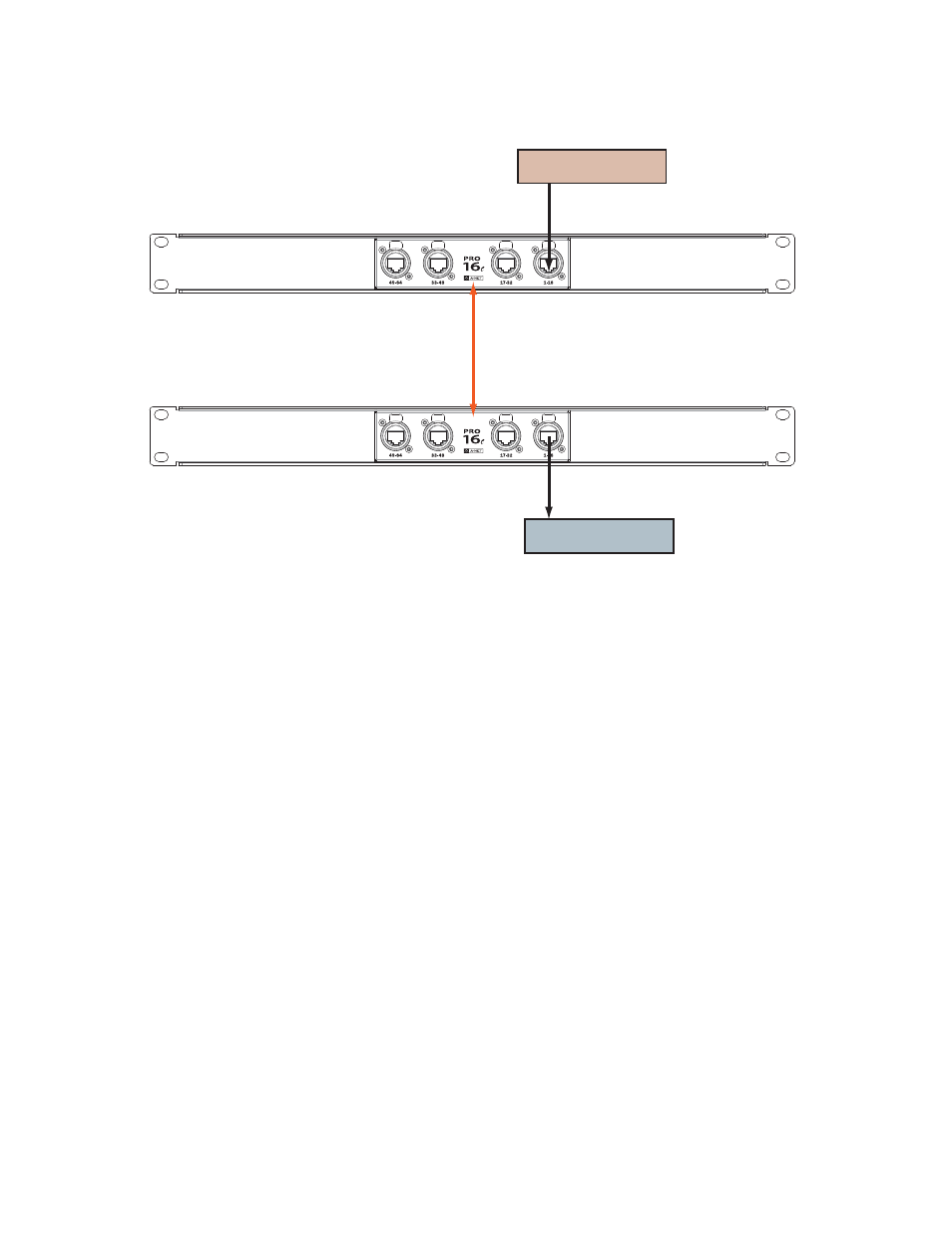
A-Net Input Device
A-Net Output Device
A-Net Bridge
(front panel)
A Pro16 input and output module each connected to port 1-16 on a pair of System Bridges
Once the A-Net Bridge ports on the two System Bridges are connected with a Cat-5 cable, the A-Net data
can flow between the two products and a simple 16-in, 16-out digital snake has been created.
Following the pattern from example above, connect additional Pro16 I/O devices to the remaining pairs
of ports (17-32, 33-48, and 49-64)) on the System Bridge. A complete digital snake system, in this case a
48 x 16 configuration, would look like the diagram that follows:
15
SB4 S
yStem
B
ridge
U
Ser
g
Uide