Electrical connections, Aw900r4 user’s manual – AvaLAN Wireless AW900R4 User Manual
Page 4
PAGE 4
Technical support (650) 384-0000
www.avalanwireless.com
AW900R4
User’s Manual
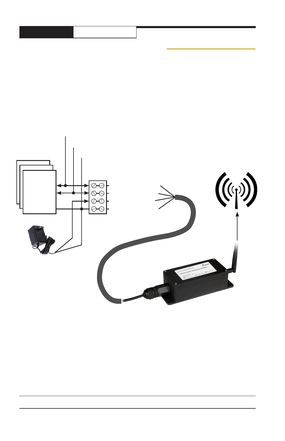
Electrical Connections
The AW900R4 900 MHz Outdoor Wireless RS-485 Radio includes the following items:
• AW900R4 Radio
• AW2-900 Omnidirectional Antenna
• RJ-45 to Screw Terminal 30 foot cable
• DB-9 Female to Screw Terminal breakout adapter
• 20” USB to Mini-USB Adapter Cable
• 120VAC to 12 VDC Wall Hanger Power Supply
To power up a radio, make connections to it as shown in this diagram:
Connect all radios in the wireless link to their respective RS-485 devices, power
supplies and antennas in similar fashion. The radios use an RJ-45 connector for
data because they leverage the weatherproof solution already developed for our
Ethernet products. If the length or termination method of the cable supplied does
not meet your needs, an inexpensive CAT5 cable can be used by installing an RJ-45
plug on the radio end and terminating the other end however you need.
Provide some physical separation between two radio module antennas — at least
ten feet. If their antennas are in close proximity, the module radio receivers will be
overloaded, causing degradation in the bit error rate and slower link performance.
900 MHz
Antenna
RS-485
Data
Source(s)
White-striped
wire: +12 VDC
Plain black
wire
485- (orange twisted pair)
+
12 (blue twisted pair)
485+ (green twisted pair)
GND (brown twisted pair)
Terminal Block
30’ Cable
Screw Terminals
to RJ-45
Weatherproof
Sealing Gland
12 VDC Power Supply
Inverting
line “A”
Common
Non-Inverting
line “B”