Ducting, Line voltage electrical connections, Warning – Steffes 4140 Simplified Installation Guide User Manual
Page 3
7
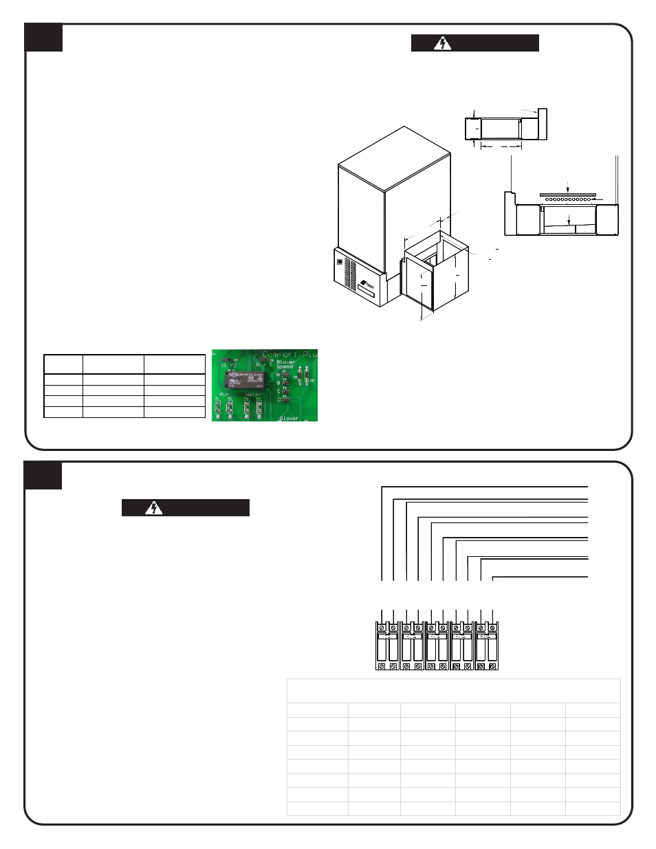
DUCTING
4100 Series systems are factory configured for a left-to-right
or right-to-left airflow. For a down flow configuration, order
Down Flow Kit #1301578.
1. Unbox supply air blower plenum assembly.
2. Remove and discard metal plate securing supply air
blower to plenum assembly.
3. Attach plenum support bracket to supply air side using
blunt tip screws.
4. Attach supply blower wiring harness to blower. Place
excess wiring in base below radiant heat shield.
5. Verify blower is installed with motor facing away from
system.
6. Attach supply air blower plenum. Drill two 1/8" holes per
edge. Use self-tapping screws.
7. Connect return air and supply air ducting. The air holes
directly above the air outlet on the right side MUST be
contained in the duct system.
8. If necessary, adjust supply air blower speed by using the
chart below.
9. The W/E jumper MUST be in the ON position or the blower
will not operate with an E call from the thermostat.
When interfacing with a heat pump, the A-Coil MUST
be placed on the return air side.
To maintain a room temperature of 85
o
F or less in
the mechanical room, a 24" x 24" opening can be
installed in the area or a 6" x 6" non-closing register
can be cut into the return air duct. Refer to Place-
ment and Clearance Requirements section of
Owners and Installers Manual for more information.
Supply Air Plenum Support Bracket
Radiant Heat Shield
Air
Holes
25
1
16
"
24
1
4
"
8 3/8"
(± 1/4")
22 5/8"
M
A
M
STE FFES
P
M
18" (
1
2
HP Blower)
22
1
2
" (1 HP Blower)
10
1
2
22
5
16
8
LINE VOLTAGE ELECTRICAL CONNECTIONS
LIN
E
2
LIN
E
1
LIN
E
2
LIN
E
1
CHARGE CIRCUIT #3
CHARGE CIRCUIT #2
CHARGE CIRCUIT #1
BLOWERS/CONTROLS CIRCUIT
CHARGE CIRCUIT #4
(MODEL 4130 and 4140 ONLY)
LIN
E
2
LIN
E
1
LIN
E
1
LIN
E
2
LIN
E
1
LIN
E
2
Comfort Plus
Circuit Breakers
To Servi
ce (B
rea
ker) Panel
CIRCUIT PHASING CONNECTIONS
HAZARDOUS VOLTAGE: Risk of electric shock. Can
cause injury or death. DO NOT operate the Comfort
Plus heating system without ducting installed to both
the air inlet and outlet.
To ensure proper operation and safety,
all line voltage circuits must be segre-
gated from low voltage wiring.
To reduce electromagnetic fields associ-
ated with electrical circuits and to avoid
induced voltage on sensors and elec-
tronic devices, the circuit phases MUST
be alternated as shown on the left.
DO NOT install any wiring in the line
voltage compartment of the Comfort
Plus heating system unless it is rated for
line voltage.
WARNING
WARNING
WARNING
WARNING
WARNING
WARNING
WARNING
WARNING
WARNING
WARNING
Jumper
½ HP Variable
Speed CFM
1 HP Variable
Speed CFM
A 1000 1200
B 1200 1400
C 1400 1600
D 1600 2000
External static pressure should
not exceed .75 water column.
Model
Control Crct Chrg Crct #1 Chrg Crct #2 Chrg Crct #3 Chrg Crct #4
4120 - 14.0kW
7.00
21.88
21.88
14.58
N/A
4120 - 19.2kW
7.00
30.00
30.00
20.00
N/A
4120 - 24.8kW
7.00
38.75
38.75
25.83
N/A
4130 - 28.8kW
7.00
30.00
30.00
30.00
30.00
4130 - 37.2kW
7.00
38.75
38.75
38.75
38.75
4140 - 38.4kW
7.00
40.00
40.00
40.00
40.00
4140 - 45.6kW
7.00
47.50
47.50
47.50
47.50
Full Load Current
Show n for 240VAC only. Circuit deration not included.
HAZARDOUS VOLTAGE: Risk of electric shock. Can cause injury
or death. Do not energize the Comfort Plus heating system until
installation is complete.
1. Route all line voltage wires through knockout(s) and into electrical
panel.
2. Make proper field wiring connections phasing circuits as shown on
the left. Reference the Unit Identification Label for circuit information.