Heating element and air channel installation, Important, Warning – Steffes 4140 Simplified Installation Guide User Manual
Page 2
4
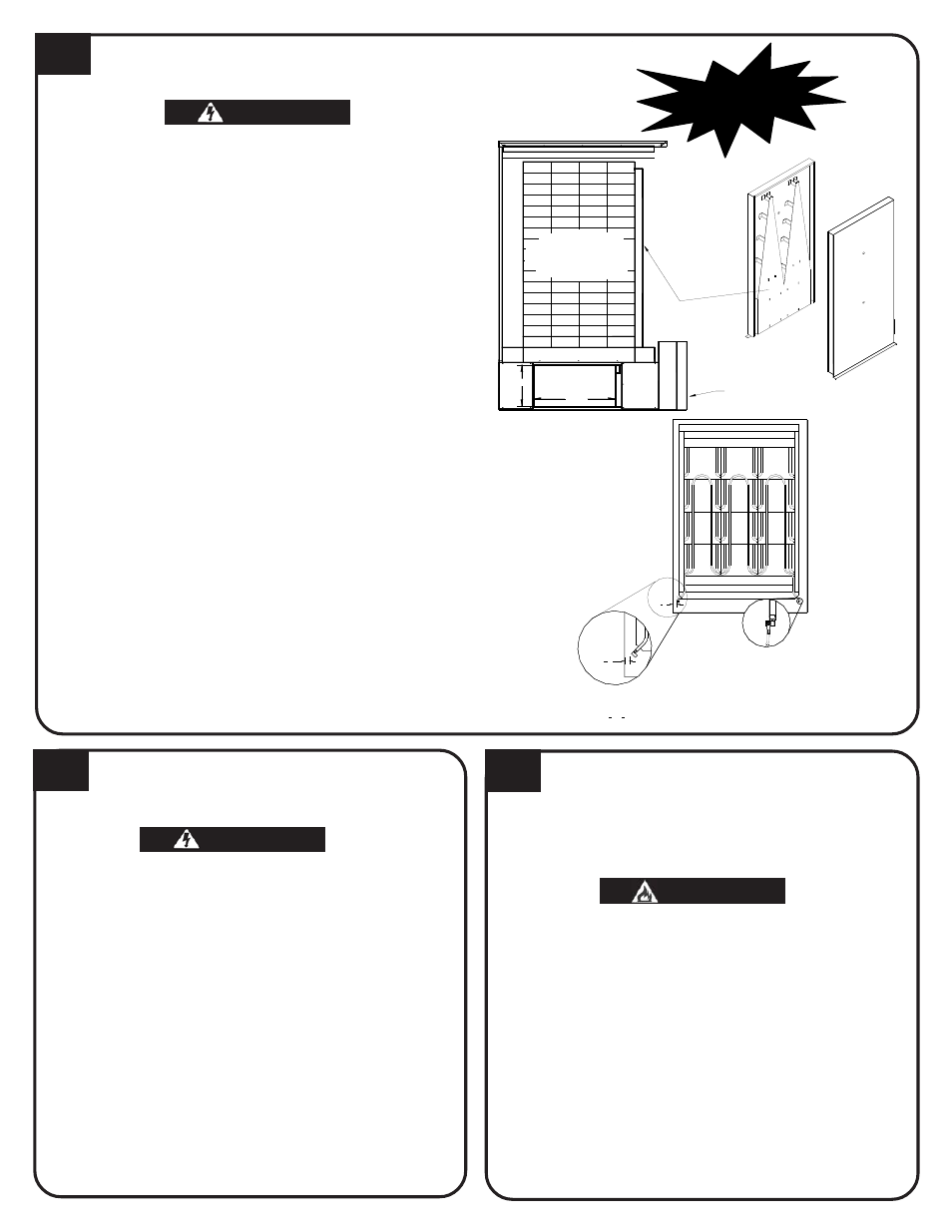
HEATING ELEMENT AND AIR CHANNEL INSTALLATION
3
4
"
3
4
"
Required Clearance
Between Element Termination and
Metal Panels is
1
2
" (
3
4
" Nominal).
Element
Connection
WARNING
WARNING
WARNING
WARNING
WARNING
HAZARDOUS VOLTAGE: Risk of electric shock. Can
cause injury or death.
DO NOT remove electrical panel cover while system
is energized.
Elements MUST be positioned properly to avoid
short circuiting them against any surfaces within
system.
Use care when making connections to avoid ele-
ment damage.
1. Insert heating elements between brick layers until
element ends embed into side cutouts of brick cavity.
Elements MUST be installed with threaded screw tabs on
wire connection terminals pointing forward and down.
2. Install front air channel with air deflectors (arrow shaped
pieces) facing inward and narrow ends of deflectors
pointing up. Place top of air channel in first.
3. Lower insulation blankets back into position, one at a
time. Tuck sides into edges, corners and around exposed
portions of heating elements.
4. Install galvanized panel. Slide the top inside the upper lip
of top painted panel. Bottom rests on the outside of the
brick cavity.
5. Connect wiring harnesses to heating elements using
screws in element screw kit. Install screws with heads up
and threads pointing down. Tighten screws to 14 in lbs.
6. Check non-insulated element connections to make sure
they do not come within 1/2" of any surface.
5
6
BRICK CORE TEMPERATURE
SENSOR(S) INSTALLATION
AIR CONDITIONER/HEAT PUMP
INTERFACE
Risk of improper operation. Proper installation of
the brick core temperature sensor(s) is critical to
the operation of the Comfort Plus heating system.
Read and follow installation instructions carefully.
1. Remove screw(s) by temperature sensor hole(s) in
galvanized front panel.
2. Insert temperature sensor(s) through hole(s). Sensor(s)
must pass through blanket insulation and into brick
core.
3. Install screw(s) into galvanized front panel to hold
sensor(s) and provide electrical ground connection.
4. Inspect sensor wiring for possible short circuiting
hazards.
5. Install painted front panel.
NOTE: Models 4130 and 4140 have an upper and a lower
temperature sensor. The upper core sensor MUST be
installed in the upper core for proper operation.
When interfacing a heat pump with the Comfort Plus, the A-
coil MUST be placed in the return air plenum.
Risk of fire. Any one ducting system MUST NOT
contain more than one air handling (blower)
system.
The Comfort Plus system can accommodate most heat
pump or air conditioner indoor coils provided the heat
pump or air conditioner is sized in accordance to supply air
delivery rates of the Comfort Plus.
1/2 HP variable speed accommodates most 1.5 to 4
ton heating/cooling systems
1 HP variable speed accommodates most 3 to 5 ton
heating/cooling systems
WARNING
WARNING
WARNING
WARNING
WARNING
WARNING
WARNING
WARNING
WARNING
WARNING
20.3"
10.4"
BRICK
CORE
SIDE VIEW
Front Air Channel
Electrical
Panel
Br
ick
S
ide
B
ott
om
Ba
ck
V
iew
Fr
on
t V
iew
IMPORTANT